STOP AND START SYSTEM, Diagnostic DTC:P0617
| DTC Code | DTC Name |
|---|---|
| P0617 | Starter Relay Circuit High |
DESCRIPTION
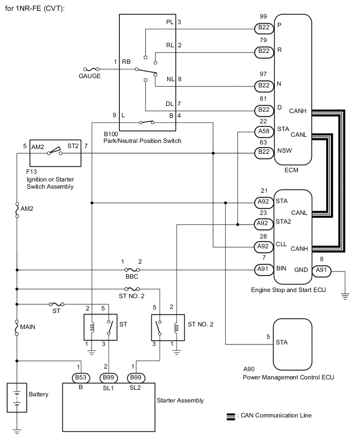
- for CVT
When the engine is started by stop and start control, the engine stop and start ECU sends a starter pinion activation relay voltage (STA voltage) to the starter pinion activation relay, and then sends a starter motor activation relay voltage (STA2 voltage) to the starter motor activation relay via the delay circuit inside the engine stop and start ECU, controlling the starter.
If overcurrent is detected in any relay, P0617 is stored, and the stop and start cancel indicator light blinks.
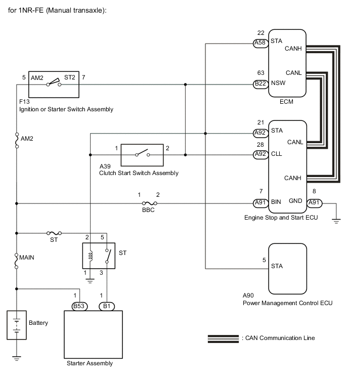
- for Manual Transaxle
When the stop and start system is activated, the engine stop and start ECU sends starter operation voltage (STA voltage) to the starter relay (ST relay) and controls the starter assembly.
If overcurrent is detected in any relay, P0617 is stored, and the stop and start cancel indicator light blinks.
| DTC No. | DTC Detection Condition | Trouble Area |
|---|---|---|
| P0617 | Both of the following conditions continue for 1 second (1 trip detection logic):
|
|
-
*1: for CVT
CONFIRMATION DRIVING PATTERN
-
After troubleshooting, perform the following steps to recheck for DTCs.
Tech Tips
-
If the cable is disconnected from the negative (-) battery terminal, stop and start control is prohibited until refresh charge is completed. After connecting the cable, drive the vehicle until refresh charge is completed and stop and start control is permitted (approximately 15 to 40 minutes).
-
Allow the engine to idle for 3 minutes after it is warmed up and check that the engine idle speed is within 50 rpm of the target idle speed.
-
for Manual transaxle
-
Connect the GTS to the DLC3.
-
Turn the ignition switch to ON and turn the GTS on.
-
Clear the DTCs Click here.
-
Start the engine and warm it up.
-
Drive the vehicle at 7 km/h (4.3 mph) or more.
CAUTION:
When performing the confirmation driving pattern, obey all speed limits and traffic laws.
-
Stop the vehicle, move the shift lever to neutral and release the clutch pedal.
-
Keep the engine stopped by stop and start control for 1 second or more.
-
Depress the clutch pedal and start the engine.
Tech Tips
If the engine cranks slowly when the engine is restarted, it can be determined that battery voltage is low.
-
Check that DTCs are not output Click here.
-
-
for CVT
-
Connect the GTS to the DLC3.
-
Turn the ignition switch to ON and turn the GTS on.
-
Clear the DTCs Click here.
-
Start the engine and warm it up.
-
Drive the vehicle at 7 km/h (4.3 mph) or more.
CAUTION:
When performing the confirmation driving pattern, obey all speed limits and traffic laws.
-
Depress the brake pedal and stop the vehicle.
-
Keep the engine stopped by stop and start control for 1 second or more (Keep the shift lever in D).
-
Release the brake pedal with the shift lever in D to start the engine.
Tech Tips
If the engine cranks slowly when the engine is restarted, it can be determined that battery voltage is low.
-
Check that DTCs are not output Click here.
-
-
-
Check if the stop and start system operates normally.
Tech Tips
If the cable is disconnected from the negative (-) battery terminal, stop and start control is prohibited until refresh charge is completed. After connecting the cable, drive the vehicle until refresh charge is completed and stop and start control is permitted (approximately 15 to 40 minutes).
-
for Manual transaxle
-
Start the engine and warm it up.
-
Turn the air conditioning system off.
-
Drive the vehicle at 7 km/h (4.3 mph) or more.
CAUTION:
When performing the confirmation driving pattern, obey all speed limits and traffic laws.
-
Stop the vehicle, move the shift lever to neutral and release the clutch pedal.
-
Allow the engine to stop by stop and start control.
-
Depress the clutch pedal and start the engine.
-
-
for CVT
-
Start the engine and warm it up.
-
Turn the air conditioning system off.
-
Drive the vehicle at 7 km/h (4.3 mph) or more.
CAUTION:
When performing the confirmation driving pattern, obey all speed limits and traffic laws.
-
Depress the brake pedal and stop the vehicle.
-
Keep the engine stopped by stop and start control for 1 second or more (Keep the shift lever in D).
-
Release the brake pedal with the shift lever in D to start the engine.
-
-
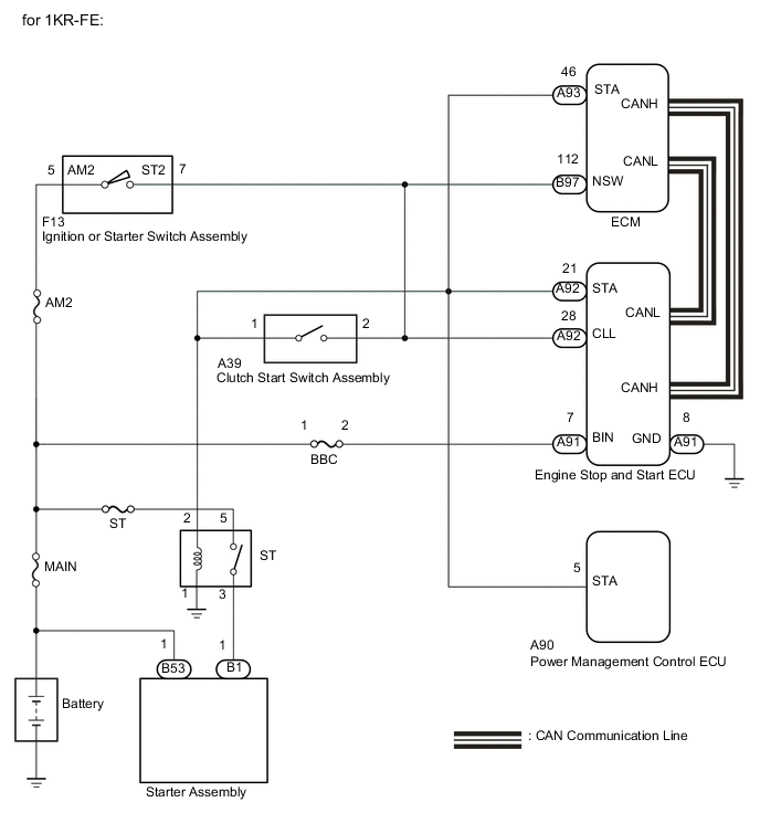
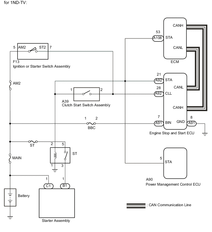
WIRING DIAGRAM
CAUTION / NOTICE / HINT
Note
-
Before replacing the engine stop and start ECU, read the number of starter operations and write it into a new engine stop and start ECU Click here.
-
After replacing the engine stop and start ECU or air conditioning amplifier assembly, reset and perform learning of the air conditioning information in the engine stop and start ECU Click here.
-
After replacing the engine stop and start ECU or airbag sensor assembly, clear and calibrate the deceleration sensor zero point in the engine stop and start ECU Click here.
-
Inspect the fuses for circuits related to this system before performing the following inspection procedure.
Tech Tips
Using the GTS, read the freeze frame data before troubleshooting. System condition information is recorded as freeze frame data the moment a DTC is stored. This information can be useful when troubleshooting Click here.
PROCEDURE
-
CHECK HARNESS AND CONNECTOR (ENGINE STOP AND START ECU - BBC FUSE)
-
Disconnect the A91 engine stop and start ECU connector.
-
Remove the BBC fuse from engine room relay block and junction block assembly.
-
Measure the resistance according to the value(s) in the table below.
Standard Resistance Tester Connection Condition Specified Condition A91-7 (BIN) - BBC fuse terminal 2 Always Below 1 Ω A91-7 (BIN) or BBC fuse terminal 2 - Body ground Always 10 kΩ or higher Result Result Proceed to OK (for CVT) A OK (for Manual Transaxle) B NG C
B 
CHECK HARNESS AND CONNECTOR (ENGINE STOP AND START ECU - ST RELAY) Click here
C 
REPAIR OR REPLACE HARNESS OR CONNECTOR
A 
-
-
CHECK HARNESS AND CONNECTOR (ENGINE STOP AND START ECU - ST RELAY AND ST NO. 2 RELAY)
-
Disconnect the A91 and A92 engine stop and start ECU connectors.
-
Disconnect the A58 ECM connector.
-
Disconnect the A90 power management control ECU connector.
-
Disconnect the B100 park/neutral position switch connector.
-
Remove the ST relay from engine room relay block.
-
Remove the ST NO. 2 relay from No. 2 engine room relay block.
-
Remove the BBC fuse from engine room relay block and junction block assembly.
-
Measure the resistance according to the value(s) in the table below.
Standard Resistance Tester Connection Condition Specified Condition A92-21 (STA) - ST relay holder 2 Always Below 1 Ω A92-23 (STA2) - ST NO. 2 relay holder 2 Always Below 1 Ω A92-21 (STA), A90-5 (STA), B100-9 (L) or ST relay holder 2 - Body ground Always Below 1 Ω A92-23 (STA2), A58-22 (STA) or ST NO. 2 relay holder 2 - Body ground Always Below 1 Ω A91-7 (BIN) - A92-21 (STA) Always 10 kΩ or higher A91-7 (BIN) - A92-23 (STA2) Always 10 kΩ or higher
NG
REPAIR OR REPLACE HARNESS OR CONNECTOR
OK
-
-
CHECK ENGINE STOP AND START ECU
-
Disconnect the engine stop and start ECU connector.
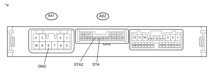
Text in Illustration *a Component with harness connected
(Engine Stop and Start ECU)
- - -
Measure the resistance according to the value(s) in the table below.
Standard Resistance Tester Connection Condition Specified Condition A92-21 (STA) - A91-8 (GND) Always 10 kΩ or higher A92-23 (STA2) - A91-8 (GND) Always 10 kΩ or higher
NG
REPLACE ENGINE STOP AND START ECU Click here
OK
-
-
INSPECT RELAY (ST RELAY, ST NO. 2 RELAY)
-
Inspect the ST relay Click here.
-
Inspect the ST NO. 2 relay Click here.
OK
USE SIMULATION METHOD TO CHECK Click here
NG
REPLACE RELAY (ST RELAY, ST NO. 2 RELAY)
-
-
CHECK HARNESS AND CONNECTOR (ENGINE STOP AND START ECU - ST RELAY)
-
Disconnect the A91 and A92 engine stop and start ECU connectors.
-
Disconnect the A58 ECM connector. (for 1NR-FE)
-
Disconnect the A93 ECM connector. (for 1KR-FE)
-
Disconnect the A108 ECM connector. (for 1ND-TV)
-
Disconnect the A90 power management control ECU connector.
-
Disconnect the A39 clutch start switch assembly (for lower) connector.
-
Remove the ST relay from engine room relay block.
-
Remove the BBC fuse from engine room relay block and junction block assembly.
-
Measure the resistance according to the value(s) in the table below.
Standard Resistance for 1NR-FE Tester Connection Condition Specified Condition A92-21 (STA) - ST relay holder 2 Always Below 1 Ω A92-21 (STA), A90-5 (STA), A58-22 (STA) or ST relay holder 2 - Body ground Always Below 1 Ω A91-7 (BIN) - A92-21 (STA) Always 10 kΩ or higher for 1KR-FE Tester Connection Condition Specified Condition A92-21 (STA) - ST relay holder 2 Always Below 1 Ω A92-21 (STA), A90-5 (STA), A93-46 (STA) or ST relay holder 2 - Body ground Always Below 1 Ω A91-7 (BIN) - A92-21 (STA) Always 10 kΩ or higher for 1ND-TV Tester Connection Condition Specified Condition A92-21 (STA) - ST relay holder 2 Always Below 1 Ω A92-21 (STA), A90-5 (STA), A108-53 (STA) or ST relay holder 2 - Body ground Always Below 1 Ω A91-7 (BIN) - A92-21 (STA) Always 10 kΩ or higher
NG
REPAIR OR REPLACE HARNESS OR CONNECTOR
OK
-
-
CHECK ENGINE STOP AND START ECU
-
Disconnect the engine stop and start ECU connector.
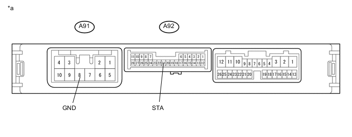
Text in Illustration *a Component with harness connected
(Engine Stop and Start ECU)
- - -
Measure the resistance according to the value(s) in the table below.
Standard Resistance Tester Connection Condition Specified Condition A92-21 (STA) - A91-8 (GND) Always 10 kΩ or higher
NG
REPLACE ENGINE STOP AND START ECU Click here
OK
-
-
INSPECT RELAY (ST RELAY)
-
Inspect the ST relay (for 1NR-FE) Click here.
-
Inspect the ST relay (for 1KR-FE) Click here.
-
Inspect the ST relay (for 1ND-TV) Click here.
OK
USE SIMULATION METHOD TO CHECK Click here
NG
REPLACE RELAY (ST RELAY)
-