STOP AND START SYSTEM, Diagnostic DTC:P161D
| DTC Code | DTC Name |
|---|---|
| P161D | Starter Delay Circuit |
DESCRIPTION
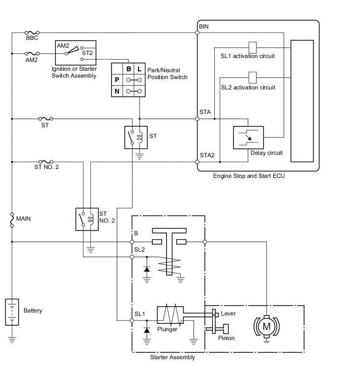
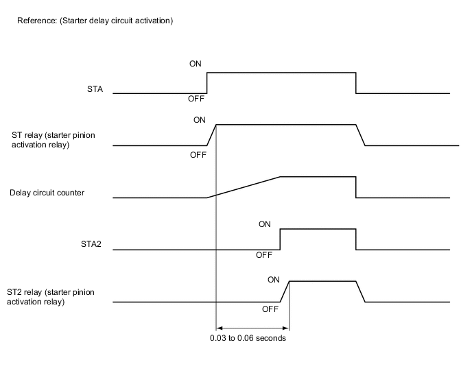
By using the starter delay circuit, the engine stop and start ECU can activate the ST NO. 2 relay (for starter motor operation) after activating the ST relay (for starter pinion operation) to operate the starter assembly.
By monitoring the condition of the ST relay (for starter pinion operation) and ST NO. 2 relay (for starter motor operation), the engine stop and start ECU detects if the transistor of the starter delay circuit is stuck. If the transistor of the starter delay circuit is stuck on, the engine stop and start ECU blinks the stop and start cancel indicator light and stores DTC P161D. If the transistor of the starter delay circuit is stuck on, the ST relay (for starter pinion operation) and ST NO. 2 relay (for starter motor operation) will be activated simultaneously.
| DTC No. | DTC Detection Condition | Trouble Area |
|---|---|---|
| P1610 |
|
Engine Stop and Start ECU |
CONFIRMATION DRIVING PATTERN
-
After troubleshooting, perform the following steps to recheck for DTCs.
Tech Tips
-
If the cable is disconnected from the battery terminal, stop and start control is prohibited until refresh charge is completed.
In this case, let the vehicle idle to complete the refresh charge. The refresh charge is complete when the Data List item Status of Battery Charge Control changes from "Refresh Charge Mode". (Usually, idling the engine for 5 to 60 minutes with the battery temperature at 11°C (52°F) or higher, the refresh charge will be completed.)
-
If the GTS is not available and the Data List item Status of Battery Charge Control cannot be checked, charge the battery by idling the engine for approximately 5 to 60 minutes or driving the vehicle, and then drive the vehicle and check that stop and start control operates. If the engine is started with the hood open, the system determines that a jump start has occurred. Therefore, make sure that the hood is closed before starting the engine and driving the vehicle.
-
After the refresh charge completes, turn the ignition switch off, wait for at least 30 seconds, and then start the engine again. If the vehicle enters refresh charge mode again while the engine is idling, the initial refresh charge did not properly complete, so wait for the refresh charge to complete.
-
Allow the engine to idle for 3 minutes after it is warmed up and check that the engine idle speed is within 50 rpm of the target idle speed.
-
Connect the GTS to the DLC3.
-
Turn the ignition switch to ON and turn the GTS on.
-
Clear the DTCs Click here.
-
Start the engine and warm it up.
-
Drive the vehicle at 7 km/h (4.3 mph) or more.
CAUTION:
When performing the confirmation driving pattern, obey all speed limits and traffic laws.
-
Depress the brake pedal and stop the vehicle.
-
Keep the engine stopped by stop and start control for 1 second or more (Keep the shift lever in D).
-
Release the brake pedal with the shift lever in D to start the engine.
Tech Tips
If the engine cranks slowly when the engine is restarted, it can be determined that battery voltage is low.
-
Check that DTCs are not output Click here.
-
-
Check if the stop and start system operates normally.
Tech Tips
-
If the cable is disconnected from the battery terminal, stop and start control is prohibited until refresh charge is completed.
In this case, let the vehicle idle to complete the refresh charge. The refresh charge is complete when the Data List item Status of Battery Charge Control changes from "Refresh Charge Mode". (Usually, idling the engine for 5 to 60 minutes with the battery temperature at 11°C (52°F) or higher, the refresh charge will be completed.)
-
If the GTS is not available and the Data List item Status of Battery Charge Control cannot be checked, charge the battery by idling the engine for approximately 5 to 60 minutes or driving the vehicle, and then drive the vehicle and check that stop and start control operates. If the engine is started with the hood open, the system determines that a jump start has occurred. Therefore, make sure that the hood is closed before starting the engine and driving the vehicle.
-
After the refresh charge completes, turn the ignition switch off, wait for at least 30 seconds, and then start the engine again. If the vehicle enters refresh charge mode again while the engine is idling, the initial refresh charge did not properly complete, so wait for the refresh charge to complete.
-
Start the engine and warm it up.
-
Turn the air conditioning system off.
-
Drive the vehicle at 7 km/h (4.3 mph) or more.
CAUTION:
When performing the confirmation driving pattern, obey all speed limits and traffic laws.
-
Depress the brake pedal and stop the vehicle.
-
Keep the engine stopped by stop and start control for 1 second or more (Keep the shift lever in D).
-
Release the brake pedal with the shift lever in D to start the engine.
-
WIRING DIAGRAM
Refer to P0617 Click here.
CAUTION / NOTICE / HINT
Note
-
Before replacing the engine stop and start ECU, read the number of starter operations and write it into a new engine stop and start ECU Click here.
-
After replacing the engine stop and start ECU or air conditioning amplifier assembly, reset and perform learning of the air conditioning information in the engine stop and start ECU Click here.
-
After replacing the engine stop and start ECU or airbag sensor assembly, clear and calibrate the deceleration sensor zero point in the engine stop and start ECU Click here.
Tech Tips
Using the GTS, read the freeze frame data before troubleshooting. System condition information is recorded as freeze frame data the moment a DTC is stored. This information can be useful when troubleshooting Click here.
PROCEDURE
-
INSPECT ENGINE STOP AND START ECU (STA, STA2 SIGNAL)
-
Connect an oscilloscope to terminals A92-21 (STA), A92-23 (STA2) and A91-8 (GND).
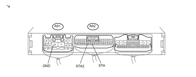
Text in Illustration *a Component with harness connected:
(Engine Stop and Start ECU)
- - -
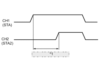
*1 0.016 seconds or more Check the waveform immediately after starting
Item Condition Tester connection A92-21 (STA) - A91-8 (GND)
A92-23 (STA2) - A91-8 (GND)
Tool Setting 10 V/DIV., 10 ms./DIV. Condition Engine starting by operating the ignition or starter switch assembly Result Tester Connection Condition Specified Condition Proceed to A92-21 (STA) - A91-8 (GND)
A92-23 (STA2) - A91-8 (GND)
Engine starting by operating the ignition or starter switch assembly Time from ST relay on to ST NO. 2 relay on 0.016 seconds or more A Time from ST relay on to ST NO. 2 relay on is less than 0.016 seconds B
A 
USE SIMULATION METHOD TO CHECK Click here
B
REPLACE ENGINE STOP AND START ECU Click here
-