STOP AND START SYSTEM, Diagnostic DTC:P0335
| DTC Code | DTC Name |
|---|---|
| P0335 | Crankshaft Position Sensor "A" Circuit |
DESCRIPTION
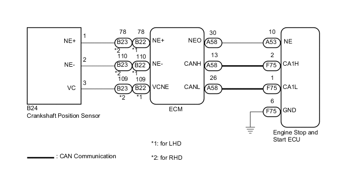
This description and the following Inspection Procedure are for DTC P0335 which is stored in the engine stop and start ECU. The crankshaft position sensor sends an engine speed signal (NE signal) to the ECM. The engine speed signal is then sent directly from the NEO terminal of the ECM to the engine stop and start ECU.
In addition the ECM sends the engine speed value to the engine stop and start ECU via CAN, and the engine stop and start ECU compares the NE signal and the engine speed to check for abnormalities in the NE signal.
If any abnormalities are detected, the engine stop and start ECU cancels Stop and Start system control.
| DTC No. | DTC Detection Condition | Trouble Area |
|---|---|---|
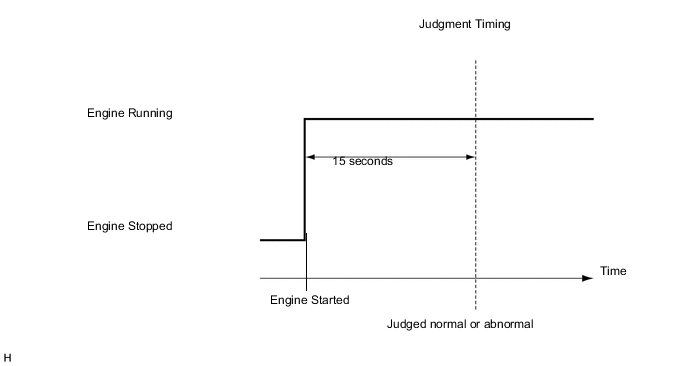
| P0335 | All of the following conditions continue for 10 seconds (1 trip detection logic):
|
|
Tech Tips
DTCs for the Stop and Start system are not cleared even if the malfunction has been repaired. After repairing the malfunction, be sure to clear the DTCs Click here.
-
After troubleshooting, perform the following steps to recheck for DTCs.
Tech Tips
-
If the battery terminal has been disconnected, the stop and start will be prohibited. In this case, drive the vehicle for 15 to 40 minutes to permit the stop and start operation.
-
Allow the engine to idle for 3 minutes after the engine warms up and check that the engine speed is within 50 rpm of the target idle speed.
-
Connect the intelligent tester to the DLC3.
-
Clear the DTCs Click here.
-
Start the engine and wait for at least 15 seconds.
-
Check that no DTCs are output Click here.
-
-
Check if the Stop and Start system operates normally.
Tech Tips
If the battery terminal has been disconnected, the stop and start will be prohibited. In this case, drive the vehicle for 15 to 40 minutes to permit the stop and start operation.
-
for Manual Transaxle
-
Warm up the engine.
-
Turn the air conditioning system off.
-
Drive the vehicle at 7 km/h (4.3 mph) or more.
-
Stop the vehicle. Move the shift lever to neutral and release the clutch pedal.
-
Check that the engine stops.
-
Depress the clutch pedal and check that the engine restarts.
-
-
for CVT
-
Warm up the engine.
-
Turn the air conditioning system off.
-
Drive the vehicle at 7 km/h (4.3 mph) or more.
-
Stop the vehicle with the shift lever in D and depressed the brake pedal.
-
Check that the engine stops.
-
Release the brake pedal and check that the engine restarts.
-
-
WIRING DIAGRAM
CAUTION / NOTICE / HINT
Note
-
If the engine stop and start ECU is being replaced, download the number of starter operations to the tester from the old ECU before removing it, and then upload the number of starter operations from the tester to the new engine stop and start ECU after installing the ECU Click here.
-
After the engine stop and start ECU is replaced or after an air conditioner kit is installed, clear the A/C information stored in the engine stop and start ECU Click here.
-
After the engine stop and start ECU or airbag sensor assembly (yaw rate sensor) is replaced, initialize and calibrate 0 point of deceleration sensor Click here.
PROCEDURE
-
CHECK FOR DTC (SFI SYSTEM)
-
Connect the intelligent tester to the DLC3.
-
Check if SFI system DTC P0335, P0337, P0338 or P0339 is output Click here.
Result Result Proceed to No SFI system DTCs are output A SFI system DTC P0335, P0337, P0338 or P0339 is output B
B 
GO TO SFI SYSTEM Click here
A 
-
-
READ VALUE USING INTELLIGENT TESTER (ENGINE SPEED (NE SIGNAL))
-
Connect the intelligent tester to the DLC3.
-
Start the engine.
-
Turn the tester on.
-
Enter the following menus: Powertrain / Stop and Start / Data List / Engine Spd (NE Signal).
-
Check the tester display to confirm that the engine speed signal is input.
OK Engine speed signal is input (the speeds displayed on the tachometer and the tester are almost the same).
OK
USE SIMULATION METHOD TO CHECK Click here
NG
-
-
CHECK HARNESS AND CONNECTOR (ECM - ENGINE STOP AND START ECU)
-
Disconnect the A58 ECM connector.
-
Disconnect the A53 engine stop and start ECU connector.
-
Measure the resistance according to the value(s) in the table below.
Standard Resistance Tester Connection Condition Specified Condition A53-10 (NE) - A58-30 (NEO) Always Below 1 Ω A53-10 (NE) - Body ground Always 10 kΩ or higher A58-30 (NEO) - Body ground Always 10 kΩ or higher -
Reconnect the A53 engine stop and start ECU connectors.
-
Reconnect the A58 ECM connectors.
NG
REPAIR OR REPLACE HARNESS OR CONNECTOR
OK
-
-
CHECK HARNESS AND CONNECTOR (ENGINE STOP AND START ECU - BODY GROUND)
-
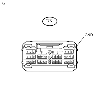
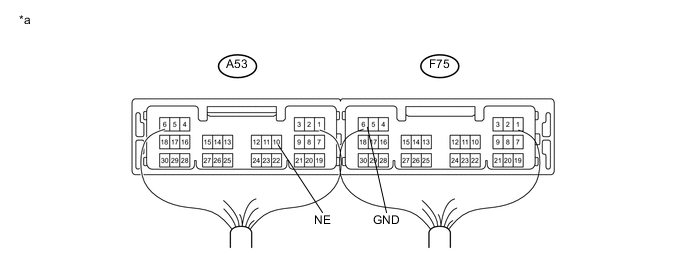
Text In Illustration *a Front view of wire harness connector
(to Engine Stop and Start ECU)
Disconnect the F75 engine stop and start ECU connector.
Standard Resistance Tester Connection Condition Specified Condition F75-6 (GND) - Body ground Always Below 1 Ω -
Reconnect the F75 engine stop and start ECU connector.
NG
REPAIR OR REPLACE HARNESS OR CONNECTOR
OK
-
-
INSPECT ENGINE STOP AND START ECU (NE SIGNAL INPUT)
-
Connect an oscilloscope to the NE and GND terminals of the engine stop and start ECU connector.
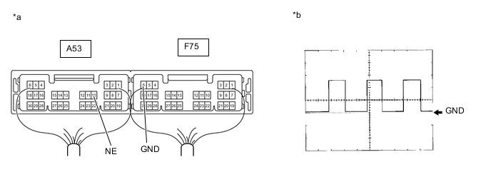
Text In Illustration *a Component with harness connected:
(Engine Stop and Start ECU)
*b Waveform -
Start the engine.
-
Check the signal waveform according to the condition(s) in the table below.
Item Condition Tester Connection Between A53-10 (NE) and F75-6 (GND) Tool Setting 5 V/DIV, 2 ms/DIV Condition Idling Tech Tips
The wavelength becomes shorter as the engine speed increases.
Result Tester Connection Condition Result Proceed to A53-10 (NE) - F75-6 (GND) Idling The correct waveform appears A Stuck at 0 to 1.5 V B Stuck at 8 to 14 V C
A
REPLACE ENGINE STOP AND START ECU Click here
C
CHECK SFI SYSTEM Click here
B
-
-
INSPECT ENGINE STOP AND START ECU (NE TERMINAL VOLTAGE)
-
Disconnect the A58 ECM connector.
-
Ignition switch to ON.
-
Measure the voltage according to the value(s) in the table below.
Text In Illustration *a Component with harness connected:
(Engine Stop and Start ECU)
- - Standard Voltage Tester Connection Condition Specified Condition A53-10 (NE) - F75-6 (GND) Ignition switch ON 8 to 14 V -
Reconnect the A58 ECM connectors.
OK
CHECK SFI SYSTEM Click here
NG
REPLACE ENGINE STOP AND START ECU Click here
-