STOP AND START SYSTEM DATA LIST / ACTIVE TEST
-
DATA LIST
Tech Tips
Using the GTS to read the Data List allows the values or states of switches, sensors, actuators and other items to be read without removing any parts. This non-intrusive inspection can be very useful because intermittent conditions or signals may be discovered before parts or wiring is disturbed. Reading the Data List information early in troubleshooting is one way to save diagnostic time.
Note
In the table below, the values listed under "Normal Condition" are reference values. Do not depend solely on these reference values when deciding whether a part is faulty or not.
-
Warm up the engine.
-
Turn the ignition switch off.
-
Connect the GTS to the DLC3.
-
Start the engine.
-
Turn the GTS on.
-
Enter the following menus: Powertrain / Stop and Start / Data List.
-
Check the values by referring to the table below.
Tech Tips
The results of a test performed on an actual vehicle are shown in the "Result of Real-vehicle Check" column. Use these values as a reference.
Stop and Start Tester Display Measurement Item/Range Normal Condition Diagnostic Note Eco Warning Stop and start indicator light status:
ON/OFF
ON: Idling stop being performed
OFF: Idling stop not being performed (When system is normal)
ON: Any malfunction occurs in the system and the stop and start indicator light is blinking. Coolant Temp Engine coolant temperature:
Min.: 16°C (60.8°F), Max.: 127°C (260.6°F)
75 to 95°C (167 to 203°F): Idling after engine warmed up This is sent from the ECM. Engine Spd (ECM) Engine speed signal from ECM via CAN communication:
Min.: -25600 rpm, Max.: 12800 rpm
-
600 to 750 rpm: Idling after engine warmed up*1, *3
-
550 to 700 rpm: Idling after engine warmed up*2, *3
-
730 to 830 rpm: Idling after engine warmed up*4
-
720 to 820 rpm: Idling after engine warmed up*5
This is sent from the ECM. Engine Spd (NE Signal) Engine speed signal from ECM via direct line:
Min.: -25600 rpm, Max.: 25599 rpm
-
600 to 750 rpm: Idling after engine warmed up*1, *3
-
550 to 700 rpm: Idling after engine warmed up*2, *3
-
730 to 830 rpm: Idling after engine warmed up*4
-
720 to 820 rpm: Idling after engine warmed up*5
The pulse signal sent is from NEO terminal of the ECM. Deceleration Sens Offset Val Deceleration sensor offset value:
Min.: -1176.008 m/s2, Max.: 1176.007 m/s2
-0.903 to 0.903 m/s2: After the deceleration sensor zero point learning completion
- Deceleration Sens Calibration Deceleration sensor calibration status:
Incmpl / Running / Compl / Err1 / Err2 / Err3
Compl: After the deceleration sensor zero point learning completion - Gradient of Road Surface Degree of road gradient:
Min.: -10.24 m/s2, Max.: 10.16 m/s2
-1.4 to 1.4 m/s2: Vehicle is stopped on level surface
- Battery Voltage Battery voltage:
Min.: 0 V, Max.: 20 V
9 to 14 V: Idling - Battery Voltage 2 VB voltage:
Min.: 0 V, Max.: 65.53 V
9 to 14 V: Idling - Battery Fluid Temperature Battery fluid temperature:
Min.: -40°C (-40°F), Max.: 100°C (212°F)
Changes according to actual temperature: Driving after engine warmed up - Battery Temp (Start) Battery temperature at engine start:
Min.: -40°C (-40°F), Max.: 100°C (212°F)
Same as temperature around battery at engine start (after engine start) - Oper Permission (AT/CVT)*1 Permissions for the stop and start control by the CVT system:
NG/OK
OK: No CVT system malfunction, and CVT fluid temperature is above 25°C This is sent from the ECM through CAN communication Oper Permission (AT/CVT 2)*1 Permissions for the stop and start control by the CVT system:
NG/OK
OK: No malfunction of the oil pump with motor assembly (continuously variable transaxle assembly) This is sent from the ECM through CAN communication Engine Type Information Information on the engine type from the SFI or ECD system:
Avail/Not Avl
Avail: Information of the engine type received from the ECM through CAN communication Not Avl is displayed if improper engine type information is received from the ECM via CAN communication. Starter Type Starter assembly type:
Other than Tandem Starter/ Tandem Starter
-
Tandem Starter*1
-
Other than Tandem Starter*2
- D Courtesy Switch Signal Driver door courtesy switch signal:
ON/OFF
ON: Driver side door opened
OFF: Driver side door closed
- Hood Courtesy Switch Hood courtesy switch signal:
ON/OFF
ON: Engine hood closed
OFF: Engine hood opened
- Neutral Switch Park/neutral position*1 or neutral position switch*2 signal:
ON/OFF
ON: Shift lever in N (neutral) or P
OFF: Shift lever not in N (neutral) or P
- Clutch Upper SW*2 Clutch start switch assembly (for upper) signal:
ON/OFF
ON: Clutch pedal fully released
OFF: Clutch pedal depressed
- Clutch Lower SW*2 Clutch start switch assembly (for lower) signal:
ON/OFF
ON: Clutch pedal released
OFF: Clutch pedal released
- Starter Starter status:
ON/OFF
ON: Cranking
OFF: Not cranking
- Pinion Gear*1 Starter pinion status:
ON/OFF
ON: Pinion active
OFF: Pinion inactive
- Starter Motor*1 Starter motor status:
ON/OFF
ON: Cranking
OFF: When not cranking
- TC Terminal TC and CG terminals of DLC3:
ON/OFF
ON: TC and CG terminals of DLC3 are connected
OFF: TC and CG terminals of DLC3 are disconnected
- Cancel Switch Stop and start cancel switch signal:
ON/OFF
ON: Stop and start cancel switch pressed
OFF: Stop and start cancel switch not pressed
- IG Switch Ignition or starter switch assembly
ON/OFF
ON: Ignition switch ON - Idle Engine idling status:
ON/OFF
ON: Accelerator pedal fully released
OFF: Accelerator pedal depressed
This is sent from the ECM. Engine Start (IG SW) Engine start by ignition or starter switch assembly
ON/OFF
ON: Engine start by ignition switch assembly operation
OFF: Except engine start by ignition switch assembly operation
Indicates starter operation by operation of the ignition switch assembly Stop Light SW (ECM) Stop light switch assembly signal from ECM:
ON/OFF
ON: Brake pedal depressed
OFF: Brake pedal released
This is sent from the ECM. Stop Light SW (ABS/VSC) Stop light switch assembly signal from brake system:
ON/OFF
ON: Brake pedal depressed
OFF: Brake pedal released
This is sent from the skid control ECU (brake actuator assembly). Fuel Heater Signal (ECD)*6 Combustion type power heater signal
ON/OFF
ON: Heater switch assembly on
OFF: Heater switch assembly off
- Engine Starter Signal Starter signal status:
ON/OFF
ON: Cranking
OFF: Not cranking
This is sent from the ECM. Buzzer Buzzer status:
ON/OFF
ON: Buzzer ON
OFF: Buzzer does not sound
Refer to warning buzzer operation conditions. Indicat. Light Eco Stop and start indicator light status:
ON/OFF
ON: Stop and start indicator light on or blinking
OFF: Stop and start indicator light off
- Oil Prs Warn Light Prohibit Oil pressure warning light status:
Permit/Prohibit
Prohibit: During engine stop by stop and start control
Permit: Not during engine stop by stop and start control
Engine stop and start ECU informs the combination meter assembly that the oil pressure warning light does not come on during engine stop by stop and start control. Brake Press Hold Req*1 Brake holding pressure requests during the stop and start control:
ON/OFF
ON: Engine is stopped by stop and start control with the shift lever in D or M
OFF: Other than when the engine is stopped by stop and start control with the shift lever in D or M
ON is displayed when there has been a brake holding pressure request during stop and start control
ON is displayed when the engine is stopped by stop and start control with the shift lever in D or M
S&S Cancel Light Code Transmission code from the engine stop and start ECU to the combination meter assembly:
Min.: 0, Max.: 255
0: Stop and start cancel indicator light off
1: Stop and start cancel indicator light on
Stop and start cancel indicator light on/blinking/off request sent to combination meter assembly. Starter Operation # Number of starter operations (count record):
Min.: 0, Max.: 1048575
- - Number of Engine Starts (IG-ON) The number of starter operations by ignition or starter switch assembly
Min.: 0, Max.: 16777215
- - Number of Engine Starts (Stop & Start) The number of starter operations by stop and start control:
Min.: 0, Max.: 16777215
- - Number of Engine Starts (Clutch Released)*2 The number of starter operations without clutch pedal being depressed:
Min.: 0, Max.: 16777215
- - Number of Engine Starts (Clutch Half-Depressed)*2 The number of starter operations with clutch pedal being depressed:
Min.: 0, Max.: 16777215
- - Vehicle Spd 1 (ABS/VSC) Vehicle speed signal from skid control ECU (brake actuator assembly) via CAN communication:
Min.: 0 km/h (0 mph), Max.: 327.67 km/h (203.6 mph)
0 km/h (0 mph): Vehicle is stopped - Steering Angle Steering angle:
Min.: -49152 deg, Max.: 49150.5 deg
- - Steering Angle Velocity Steering wheel turning speed:
Min.: -32768 deg/s, Max.: 32767 deg/s
- - Battery Current Battery current:
Min.: -125 A, Max.: 124.99 A
- - Brake Boost Pressure Brake booster pressure (absolute pressure):
Min.: 0 kPa (0 kgf/cm2,0 psi), Max.: 112 kPa (1.1 kgf/cm2, 16 psi)
Approx. 100 kPa (1.0 kgf/cm2, 15 psi): Ignition switch ON, brake pedal depressed several times (differs according to atmospheric pressure)
- Brake Negative Pressure Brake booster vacuum (negative pressure):
Min.: 0 kPa (0 kgf/cm2,0 psi), Max.: 639.98 kPa (6.53 kgf/cm2, 92.8 psi)
Approx. 0 kPa (0 kgf/cm2, 0 psi): Ignition switch ON, brake pedal depressed several times
This item cannot be checked if an error occurs in communication with the ECM. Ambient Temp Sensor Ambient temperature:
Min.: -80°C (-112°F), Max.: 79.9°C (175.8°F)
Close to ambient temperature - Stop&Start of Eng State Stop and start control status:
IG / Run / Stopreq / Stop / Restart
-
IG: Before engine started
-
Run: Engine running
-
Stopreq: Engine stop requested
-
Stop: Engine stopped (by stop and start control)
-
Restart: Engine restarted
- Stop & Start A/C Mode Selected air conditioning mode:
Undefined / Normal / S&S Prioritized
- - Idling Stop Rate Rate of the idling stop time to the entire ignition switch ON time:
Min.: 0 %, Max.: 100 %
- - Total Idling Stop Rate Rate of idling stop time to the entire ignition switch ON time:
Min.: 0%, Max.: 100%
- - Integrated Current Battery integrated current:
Min.: -268434.45 A-sec, Max.: 268435.45 A-sec
Differs according to the vehicle condition (charge/discharge conditions) Refer to "Regarding Battery Integrated Current" below for details.*7 Cranking Time Engine cranking time (in current trip) (When minimum voltage is detected at engine start):
Min.: 0 ms, Max.: 134215 ms
300 to 3000 ms: Duration of starter operation by stop and start control - Min Voltage (Cranking) Minimum battery voltage while engine cranking (in current trip):
Min.: 0 V, Max.: 327.67 V
6 to 11 V Lowest battery voltage measured in a 5 seconds period after the starter starts operating. Min Volt (After Cranking) Minimum battery voltage just after engine cranking:
Min.: 0 V, Max.: 327.67 V
6 to 11 V Minimum battery voltage while the starter operating. Master Cylinder Pressure*1 Permission of stop and start control based on the master cylinder pressure:
NG/OK
OK: Brake pedal is depressed when the engine is stopped - Status of Battery Charge Control Battery charge control status:
Change Control Coordination Mode / Stop and Start Standalone Mode / Refresh Charge Mode / Stop and Start Restriction Mode / Temperature High / Low Mode / Abnormal Mode / Battery Condition Judgment Mode / Low Temperature Mode
- - State of BBC Backup boost converter status:
Cycle Err / Overvol / Overload / Normal / Low Vol / Duty Err / S&S Sensor Electric Supply Low / S&S CPU Malfunction / BBC Overcurrent / S&S Starter Overcurrent / S&S Reduced Voltage Reset
Normal: Backup boost converter operating normally
-
Duty Err:
-
Abnormal duty ratio is detected.
-
Cycle Err:
-
Abnormal output voltage cycle is detected.
-
Low Vol:
-
A decrease in the voltage of the control IC power source within the backup boost converter is detected when ignition switch is turned to ON.
-
Overload:
-
Overcurrent is detected.
-
Overvol:
-
When the ignition switch is ON:
-
Overvoltage is detected at the control IC power source in the backup boost converter.
-
Overheating is detected at the control IC power source in the backup boost converter.
-
When boosting:
-
Error is detected in the feedback circuit in the backup boost converter.
-
Too high or low output voltage.
BBC Check Result Backup boost converter check result:
Normal/ Abnormal
Normal: backup boost converter normal Abnormal is displayed if excessive electrical load is applied to the converter at engine start. Atmosphere Pressure Atmospheric pressure (calculated value):
Min.: 0 kPa (0 kgf/cm2, 0 psi), Max.: 255 kPa (2.6 kgf/cm2, 37 psi)
Approx. 100 kPa (1.0 kgf/cm2, 15 psi): Ignition switch ON (close to actual atmospheric pressure)
ECM calculated value. EPS Load Electric power steering current:
Min.: -327.68 A, Max.: 327.67 A
Approx. 0 A: EPS assist is not activated - Accelerator Position Accelerator pedal position:
Min.: 0%, Max.: 127.5%
Actual accelerator pedal position - Shift Position*1 Shift position:
Unset/B/D/R/N/P
Shift position - Engine OFF Request Engine stop request:
ON/OFF
ON: Engine stopped due to stop and start control
OFF: Not during engine stop by stop and start control
ON is displayed when fuel-cut is performed by stop and start control, engine start is not requested, or starter is forced to operate. Manual Start during S&S*2 Manual start during stop and start control operation:
ON/OFF
- - Wrong Operation (Start) Wrong operation for engine start:
ON/OFF
OFF Unused Engine Reverse Rev. Engine reverse revolution status:
ON/OFF
- - N/Clutch Lower SW Abnoml*2 Clutch start switch assembly (for upper) abnormal status:
ON/OFF
- - N/Clutch Upper SW Abnoml*2 Clutch start switch assembly (for lower) abnormal status:
ON/OFF
- - Permit Idling Stop Engine stop standby:
ON/OFF
- - Running History Vehicle driving record:
ON/OFF
There is a record that the vehicle has driven at a speed of 2 km/h or more (no diagnostic codes output), or that the vehicle has backed away at a speed of 10 km/h or more with the shift lever in R. OFF is displayed when the engine is stopped by stop and start control, or when the shift lever is moved from a forward running position to P, N, or R Simple-IPA Available Availability of simple-IPA system on vehicle:
No/Yes
- Unused Air Suspension Available Availability of air suspension system on vehicle:
No/Yes
- Unused Welcab Available Availability of welcab system on vehicle:
No/Yes
- Unused PCS Available Availability of pre-crash safety system on vehicle:
No/Yes
- - External BBC Available Availability of external backup boost converter on vehicle:
No/Yes
- Unused ACC Available*2 Availability of radar cruise control system on vehicle:
No/Yes
- Unused Brake Hold Function Available Availability of brake hold function on vehicle:
No/Yes
- Unused Steering Angle Sensor Available Availability of steering angle sensor on vehicle:
No/Yes
- Unused Auto A/C Availability of air conditioning system on vehicle:
Without/With
With: Equipped with air conditioning system Without: Not equipped with air conditioning system Air conditioning information needs to be registered after engine stop and start ECU replacement. Eng Start Req (A/C 2) Engine start request from the air conditioning system:
ON/OFF
ON: Engine start requested to ensure air conditioning system performance
OFF: Engine start not requested to ensure air conditioning system performance
- Wheel Speed Malfunction Wheel speed sensor malfunction status:
ON/OFF
OFF: Input value from speed sensor is normal ON remains displayed when any input values from the wheel speed sensors are abnormal. Slip History*1 Slip history:
Without/With
- - E/G ECU Region Mismatch ECM region mismatch status:
ON/OFF
OFF: Engine ECU destination information is matched. ON remains displayed when the ECM for regions destinations without the stop and start system settings is detected. Power Train Output Request Method Powertrain output control request method:
Driving Force/Not Driving Force
- - Oil Pump Relay*1 Oil pump relay status:
ON/OFF
ON: Oil pump relay ON ON: On remains displayed while the engine is stopped due to stop and start control Oil Pump Status*1 Oil pump status:
ON/OFF
- ON remains displayed when the oil pump is in operation Oil Pump Duty*1 Oil pump duty:
Min.: -32767%,
Max.: 32767%
Approx. 65%: when the oil pump drives when the engine is stopped due to the stop and start control with the shift lever in D, P, N or M - State of Oil Pump*1 State of oil pump status:
Relay OFF/Stop/Starting/Running/Sig1 Err/Not Sync/Vol Err/Cur Err/Sig2 Err
- Cir Err: OPST circuit open/+B short or the power supply relay is off
Stop: Motor stops normally
Starting: Motor is starting
Running: Motor is running normally
Sig1 Err: Imperfect SIG signal
Not Sync: Imperfect motor start / loss of synchronism
Vol Err: Abnormal power supply voltage
Cur Err: Abnormal power supply current
Sig2 Err: OPST signal GND short circuit
Oper Permission (Shift D position)*1 Permission of stop and start control based on the shift lever in D or M condition:
NG/OK
OK: Vehicle being driven with shift lever in D or M - Oper Permission (Neutral Switch) Permission of stop and start control based on the park/neutral position switch*1 or neutral position switch*2 conditions:
NG/OK
- - Oper Permission (Idling) Permission of stop and start control based on the engine idle conditions:
NG/OK
OK: Engine idling (engine speed below 1250 rpm) without accelerator pedal being depressed - Oper Permission (Vehicle Speed) Permission of stop and start control based on the vehicle speed conditions:
NG/OK
OK: Vehicle is stopped OK is displayed while vehicle is stopped. Stop&Start Precondition Permission of stop and start control with all preconditions met:
ON/OFF
ON: Preconditions for stop and start control have been met Condition of permission or prohibition for terms listed below.
(ECM1, ECM2, idling, battery, ABS VSC, ABS/VSC2, IGSW, DTC, A/C, interval, after running, engine hood closed, D door closed, cancel switch, interval for starter, AT/CVT1, AT/CVT2, key operation, driver side buckle SW, ambient temperature)
For details on the preconditions, refer to System Description.
Stop&Start Precondition 2 Permission of stop and start control with all preconditions met:
ON/OFF
ON: Preconditions for stop and start control have been met Condition of permission or prohibition for terms listed below.
(idling, brake negative pressure, steering, road surface gradient, no shift operation, O/P check, starter check complete)
Oper Permission (Master Cylinder Pressure)*1 Permission of stop and start control based on the master cylinder pressure:
NG/OK
OK: Brake is applied while the vehicle is stopped - Oper Permission (ECM 1) Permission of stop and start control by the ECM:
NG/OK
OK: Stop and start control is enabled (CVT and SFI system is normal) - Oper Permission (ECM 2) Permission of stop and start control by SFI system:
NG/OK
OK: Stop and start control is enabled (SFI system is normal) This is sent from the ECM through CAN communication. Oper Permission (IG SW) Permission of stop and start control based on the ignition or starter switch assembly
NG/OK
OK: Ignition switch ON for 5 seconds - Oper Permission (DTC) Permission of stop and start control based on the DTC output conditions:
NG/OK
OK: DTC is not output - Oper Permission (Brake Negative Pressure) Permission of stop and start control based on the brake booster vacuum conditions:
NG/OK
OK: Brake booster negative pressure is between 31.5 to 56.8 kPa (0.3 to 0.6 kgf/cm2, 4.6 to 8.2 psi) for at least 1 second
- Oper Permission (Interval) Permission of stop and start control based on the engine running time conditions:
NG/OK
OK: A certain period of time has elapsed after starter operation - Oper Permission (D Door Closed) Permission of stop and start control based on the driver door open/ close conditions:
NG/OK
OK: Driver door closed - Oper Permission (Engine Hood Closed) Permission of stop and start control based on the engine hood open/ close conditions:
NG/OK
OK: Engine hood closed - Oper Permission (A/C) Permission of stop and start control based on the air conditioning conditions:
NG/OK
OK: Air conditioning conditions are met - Oper Permission (Ambient Temperature) Permission of stop and start control based on the ambient temperature:
NG/OK
OK: Ambient temperature -5°C (23°F) or higher - Oper Permission (ABS/VSC)*1 Permission of stop and start control when preconditions are met due to brake system condition:
NG/OK
OK: Stop and start control is permitted and brake system is normal, or permitted during the Active Test - Oper Permission (No Shift Operation)*1 Permission of stop and start control due to no shift lever operations:
NG/OK
OK: Shift lever has not been moved for at least 1 second - Oper Permission (After Running) Permission of stop and start control based on the initial trip conditions after the ignition switch is turned to ON:
NG/OK
OK: Vehicle has been driven at 7 km/h (4 mph) or more OK is displayed after the initial trip until the ignition switch is turned off. Oper Permission (Neutral SW OFF History)*2 Permission of stop and start control based on the shift operation history:
NG/OK
OK: Neutral position switch OFF record detected (remains ON until next stop and start system control) - Oper Permission (Clutch Upper SW OFF History)*2 Permission of stop and start control based on the clutch pedal operation history:
NG/OK
OK: Clutch pedal depressed - Oper Permission (Battery) Permission of stop and start control based on the battery conditions:
NG/OK
OK: Stop and start control is permitted based on battery conditions, or Active Test (forced permission) is performed - Oper Permission (Start Min Volt 1) Permission of stop and start control based on the battery conditions:
NG/OK
OK: Battery temperature is 0°C (32°F) or lower and the minimum voltage at starter ON is the threshold value or higher If 2 or more of Start Min Volt 1, 2, 3, or 4 are OK, stop and start control is permitted. Oper Permission (Start Min Volt 2) Permission of stop and start control based on the battery conditions:
NG/OK
OK: Battery temperature is 0°C (32°F) or higher and the minimum voltage at starter ON is the threshold value or higher If 2 or more of Start Min Volt 1, 2, 3, or 4 are OK, stop and start control is permitted. Oper Permission (Start Min Volt 3) Permission of stop and start control based on the battery conditions:
NG/OK
OK: Battery temperature is 0°C (32°F) or lower and the minimum voltage right after engine cranking is the threshold value or higher If 2 or more of Start Min Volt 1, 2, 3, or 4 are OK, stop and start control is permitted. Oper Permission (Start Min Volt 4) Permission of stop and start control based on the battery conditions:
NG/OK
OK: Battery temperature is 0°C (32°F) or higher and the minimum voltage right after engine cranking is the threshold value or higher If 2 or more of Start Min Volt 1, 2, 3, or 4 are OK, stop and start control is permitted. Oper Permission (Battery Current) Permission of stop and start control based on the battery conditions:
NG/OK
OK: Battery discharge current is -125 A or less Engine stop and start ECU calculated value. Oper Permission (Integrated Current) Permission of stop and start control based on the integrated current value conditions:
NG/OK
OK: Integrated current value is more than specified The status depend on the value of "Integrated Current", and OK/NG threshold differs according to the battery temperature.
Refer to "Regarding Battery Integrated Current" below for details.*7
Oper Prohibition (Jump Start) Prohibition of stop and start control based on the jump start conditions:
Permit/Prohibit
Prohibit: Engine started by ignition switch operation with the engine hood open When Prohibit is displayed, the stop and start control will be prohibited until the ignition switch is turned off. Oper Prohibition (Manual Start)*2 Prohibition of stop and start control based on the manual start conditions:
Permit/Prohibit
Prohibit: During manual start When Prohibit is displayed, stop and start control will be prohibited until the ignition switch is turned off.
Conditions for Manual Start:
-
Clutch start switch OFF or vehicle speed signal input
-
Neutral position switch OFF
-
Starter signal OFF
Oper Permission (Interval For Starter) Permission of stop and start control based on the conditions after engine restart:
NG/OK
OK: A maximum of 4 minutes have elapsed after engine restarted - Oper Permission (Cancel Switch) Permission of stop and start control based on the stop and start cancel switch operation:
NG/OK
OK: Stop and start control is permitted (the stop and start cancel indicator light is not illuminated) - Oper Permission (ABS/VSC 2) Permission of stop and start control by the anti-lock brake system:
NG/OK
OK: Brake control not operating - Oper Permission (Road Surface Gradient) Permission of stop and start control based on the road grade conditions:
NG/OK
Permit: Stopped on a level road (not on a steep incline) - Oper Permission (Driver Side Buckle SW) Permission of stop and start control based on the driver seat belt condition:
NG/OK
OK: The driver side buckle switch is fastened - Oper Permission (Steering) Permission of stop and start control by the power steering ECU assembly:
NG/OK
OK: EPS system is normal operated - Oper Prohibition (Shift Position Uncertain)*1 Permission of stop and start control based on the shift lever position:
Permit/Prohibit
Permit: Shift lever position determined - Oper Permission (Key Operation ) Permission of stop and start control based on the ignition or starter switch assembly
NG/OK
OK: Ignition switch assembly not operated - Oper Permission (Starter Check Complete) Permission of stop and start control based on the starter circuit self-check result:
NG/OK
OK: Stop and start control enabled (starter circuit normal) When the engine stop and start ECU is abnormal, the starter drive circuit is judged to be abnormal, and NG is displayed Oper Permission (Brake Master Pressure 0 Point)*1 Permission of stop and start control due to brake master pressure 0 point calibration completion:
NG/OK
OK: Brake master pressure 0 point calibration complete - Oper Permission (Simple-IPA Button) Permission of stop and start control by simple-IPA system:
NG/OK
- Unused Oper Prohibition (Engine F/C) Prohibition of stop and start control based on the engine fuel-cut prohibition signal:
Permit/Prohibit
Prohibit: Fuel-cut not performed on SFI system - Oper Prohibition (Air Suspension) Prohibition of stop and start control based on air suspension system:
NG/OK
- Unused Oper Prohibition (Welcab) Prohibition of stop and start control based on side lift up seat system:
NG/OK
- Unused Oper Prohibition (PCS) Prohibition of stop and start control based on pre-crash safety system:
NG/OK
- - Oper Prohibition (ACC)*2 Prohibition of stop and start control based on radar cruise control system:
NG/OK
- Unused Eng Start Req (Air Suspension/Welcab) Engine start request based on Air Suspension/Welcab signal input:
ON/OFF
- Unused Eng Start Req (Brk Negative Pressure Low) Engine start request due to low brake booster vacuum:
ON/OFF
ON: Brake booster vacuum insufficient while engine stopped by stop and start control
-
OFF is usually displayed
-
ON is displayed when the engine is started due to decreased brake booster vacuum caused by depressing the brake pedal several times
Eng Start Req (Welcab) Engine start request due to side lift up seat system
ON/OFF
- Unused Eng Start Req (IG Switch) Engine start request due to ignition or starter switch assembly
ON/OFF
ON: Engine started using ignition switch assembly while engine stopped by stop and start control - Eng Start Req (ABS/VSC)*1 Engine start request from the brake system:
ON/OFF
ON: Engine start request from the brake actuator assembly (skid control computer) - Eng Start Req (ECM) Engine start request from ECM:
ON/OFF
ON: Engine start requested by ECM - Eng Start Req (A/C) Engine start request from Air conditioning system:
ON/OFF
ON: Engine start requested by air conditioning system - Eng Start Req (Accelerator)*1 Engine start request due to accelerator pedal operation:
ON/OFF
ON: Engine start request due to accelerator pedal operation - Eng Start Req (Brake Release)*1 Engine start request due to brake release:
ON/OFF
ON: Engine start request due to brake operation - Eng Start Req (Shift Lever)*1 Engine start request due to shift lever operation:
ON/OFF
ON: Engine start request due to shift lever operation - Eng Start Req (Steering) Engine start request by power steering system:
ON/OFF
ON: Engine start request due to steering demand while the engine is stopped by stop and start control - Eng Start Req (AT/CVT)*1 Engine start request from the CVT system:
ON/OFF
ON: Engine start request from the CVT system while the engine is stopped by stop and start control - Eng Start Req (Detect DTC) Engine start request due to output of DTCs:
ON/OFF
ON: Engine start requested due to output of stop and start system DTCs - Eng Start Req (Shift Uncert)*1 Engine start request due to uncertain shift lever position:
ON/OFF
ON: Engine start request due to uncertain shift position while the engine is stopped by stop and start control - Eng Start Req (Clutch Pedal)*2 Engine start request by the clutch pedal:
ON/OFF
ON: Clutch pedal is depressed - Eng Start Req (Clutch Lower SW))*2 Engine start request by the clutch start switch assembly (for lower):
ON/OFF
ON: Clutch pedal is fully depressed - Eng Start Req (Engine Hood Open)*1 Engine start request due to opening of engine hood:
ON/OFF
ON: Engine hood open (with shift lever in N or P) while the engine is stopped by stop and start control - Eng Start Req (Battery Condition) Engine start request based on battery performance:
ON/OFF
ON: Engine start requested due to low battery voltage while the engine is stopped by stop and start control - Eng Start Req (CVT Vehicle Speed) Engine start request based on vehicle speed signal from the CVT system:
ON/OFF
- Unused Eng Start Req (ABS Vehicle Speed) Engine start request based on vehicle speed signal from the brake system:
ON/OFF
ON: Engine start requested due to speed signal while the engine is stopped by stop and start control Engine start request based on the speed sensor signal. Eng Start Req (Cancel SW) Engine start request by stop and start cancel switch (warning canceling switch assembly):
ON/OFF
ON: Engine start requested due to stop and start cancel switch operation while the engine is stopped by stop and start control - Eng Start Req (Simple-IPA) Engine start request from simple-IPA system:
ON/OFF
- Unused Eng Start Req (Courtesy SW or Buckle SW) Engine start request by courtesy switch (driver side) or driver side buckle switch:
ON/OFF
ON: Engine start requested due to courtesy switch (for driver side) or driver side buckle switch operation while the engine is stopped by stop and start control - Oper Prohibition (Panic Brake)*1 Permission of stop and start control due to sudden hard braking:
Permit/Prohibit
Permit: Vehicle is not stopped by sudden hard braking - ABS Running Operating condition of the anti-lock brake system:
ON/OFF
ON: Anti-lock brake system operating - N Position Switch*2 Neutral position switch status:
OK/NG
OK: System normal - Alternator Status Alternator power generation status:
Normal/ Abnormal
Normal: Alternator operation normal - EEPROM Error in EEPROM:
Normal/ Abnormal
Normal: EEPROM normal - Dec Sensor Calibration Deceleration sensor zero point uncalibrated:
Comp/Incomp
Comp: Deceleration sensor learning completed - Deceleration Sensor Movement Sticking of the deceleration sensor:
Normal/ Abnormal
Normal: Deceleration sensor not stuck - Neutral Switch Stuck ON*1 Fail-safe due to the neutral start switch being stuck ON:
ON/OFF
OFF: System is normal - Engine Stall History during S&S (Hood Open) Engine stall history due to opening the engine hood while the engine is stopped by stop and start control with the shift lever in D or M (neutral):
No/Yes
No: No history - Engine Stall History during S&S (Collision or Battery Voltage Low) History of engine stall due to a collision or low battery voltage when the stop and start control is operating:
No/Yes
No: No history - Engine Stall History during Engine Starting (Collision) History of engine stall due to a collision while the engine is stopped by stop and start control:
No/Yes
No: No history - Engine Start Fail History of engine restart failure by stop and start control:
No/Yes
No: No history - NE Sensor Circuit Open2 Malfunction in the crank position sensor circuit:
ON/OFF
OFF: System is normal ON: No engine speed input at engine start. Neutral Switch Stuck OFF*1 Fail-safe due to the neutral start switch being stuck ON:
ON/OFF
ON: System is normal - O/P Power Supply Voltage Low*1 Malfunction in oil pump with motor assembly (continuously variable transaxle assembly):
Normal/Abnormal
- - Brk Boost Malfunc 1 Fail-safe operation due to malfunction in the vacuum sensor assembly:
OK/NG
OK: System is normal Fail-safe operation due to sticking of the vacuum sensor assembly (a change in the sensor value is small when STP signal changes from ON to OFF). Brk Boost Malfunc 2 Fail-safe operation due to malfunction in the vacuum sensor assembly:
OK/NG
OK: System is normal Fail-safe operation due to sticking of the vacuum sensor assembly (a change in the sensor value is small, even though the vehicle speed has increased from 0 km/h (0 mph) to 30 km/h (18.6 mph) 30 times). Comm Err with Welcab*1 Fail-safe operation due to communication error with welcab ECU:
ON/OFF
- Unused N Position Voltage Status*2 Malfunction in the neutral position switch:
Normal/Hi/Low
Normal: Neutral position switch voltage normal - Num of Current Code Number of currently stored DTCs:
Min.: 0, Max.: 255
- - Number of Oper Prohibition (ECM 1) Number of stop and start control prohibitions when ECM conditions are not met:
Min.: 0, Max.: 4294967295
- - Number of Oper Prohibition (ECM 2) Number of stop and start control prohibitions due to SFI system:
Min.: 0, Max.: 4294967295
- - Number of Oper Prohibition (Engine F/C) Number of stop and start control prohibitions due to fuel-cut:
Min.: 0, Max.: 4294967295
- - Number of Oper Prohibition (Jump Start) Number of stop and start control prohibitions due to jump start:
Min.: 0, Max.: 4294967295
- - Number of Oper Prohibition (Engine Hood Closed) Number of stop and start control prohibitions due to open engine hood:
Min.: 0, Max.: 4294967295
- - Number of Oper Prohibition (AT/CVT 1)*1 Number of stop and start control prohibitions due to continuously variable transaxle system condition:
Min.: 0, Max.: 4294967295
- - Number of Oper Prohibition (AT/CVT 2)*1 Number of stop and start control prohibitions due to continuously variable transaxle system condition:
Min.: 0, Max.: 4294967295
- - Number of Oper Prohibition (Possible Clutch Lower SW Abnormality)*2 Number of stop and start control prohibitions due to clutch start switch assembly (for lower) malfunction:
Min.: 0, Max.: 4294967295
- - Number of Oper Prohibition (Possible Clutch Upper SW Abnormality)*2 Number of stop and start control prohibitions due to clutch start switch assembly (for upper) malfunction:
Min.: 0, Max.: 4294967295
- - Number of Oper Prohibition (Neutral SW OFF History)*2 Number of stop and start control prohibitions due to neutral start switch:
Min.: 0, Max.: 4294967295
- - Number of Oper Prohibition (Clutch Upper SW OFF History)*2 Number of stop and start control prohibitions due to clutch start switch assembly (for upper):
Min.: 0, Max.: 4294967295
- - Number of Oper Prohibition (Battery) Number of stop and start control prohibitions due to battery condition:
Min.: 0, Max.: 4294967295
- - Number of Oper Prohibition (Start Min Volt) Number of stop and start control prohibitions due to battery condition:
Min.: 0, Max.: 4294967295
- - Number of Oper Prohibition (Battery Current) Number of stop and start control prohibitions due to battery condition:
Min.: 0, Max.: 4294967295
- - Number of Oper Prohibition (Integrated Current) Number of stop and start control prohibitions due to battery condition:
Min.: 0, Max.: 4294967295
- - Number of Oper Prohibition (A/C) Number of stop and start control prohibitions due to air conditioning condition:
Min.: 0, Max.: 4294967295
- - Number of Oper Prohibition (Ambient Temperature) Number of stop and start control prohibitions due to ambient temperature condition:
Min.: 0, Max.: 4294967295
- - Number of Oper Prohibition (ABS/VSC 1)*1 Number of stop and start control prohibitions due to brake system permission conditions:
Min.: 0, Max.: 4294967295
- - Number of Oper Prohibition (ABS/VSC 2) Number of stop and start control prohibitions due to anti-lock brake system condition:
Min.: 0, Max.: 4294967295
- - Number of Oper Prohibition (ABS Running) Number of stop and start control prohibitions due to anti-lock brake system operation:
Min.: 0, Max.: 4294967295
- - Number of Oper Prohibition (Panic Brake)*1 Number of stop and start control prohibitions due to braking:
Min.: 0, Max.: 4294967295
- - Number of Oper Prohibition (Brake Negative Pressure) Number of stop and start control prohibitions due to brake negative pressure condition:
Min.: 0, Max.: 4294967295
- - Number of Oper Prohibition (Stop&Start Precondition1) Number of stop and start control prohibitions due to precondition 1:
Min.: 0, Max.: 4294967295
- Condition of permission or prohibition for terms listed below.
(ECM1, ECM2, idling, battery, ABS/VSC, ABS/VSC2, IGSW, DTC, A/C, interval, after running, engine hood closed, D door closed, cancel switch, interval for starter, key operation, AT/CVT, AT/CVT2, driver side buckle SW, ambient temperature)
For details on the preconditions, refer to System Description.
Number of Oper Prohibition (Stop&Start Precondition2) Number of stop and start control prohibitions due to precondition 2:
Min.: 0, Max.: 4294967295
- Condition of permission or prohibition for terms listed below.
(idling, brake negative pressure, steering, road surface gradient, no shift operation, O/P check, starter check complete)
Number of Oper Prohibition (DTC) Number of stop and start control prohibitions due to DTC output:
Min.: 0, Max.: 4294967295
- - Number of Oper Prohibition (Abnormal Wheel Speed Sensor Inputs) Number of stop and start control prohibitions due to abnormal vehicle speed signal input:
Min.: 0, Max.: 4294967295
- - Number of Oper Prohibition (Deceleration Sensor Abnormal) Number of stop and start control prohibitions due to deceleration sensor malfunction:
Min.: 0, Max.: 4294967295
- - Number of Oper Prohibition (Interval For Starter) Number of stop and start control prohibitions due to starter fail-safe operation:
Min.: 0, Max.: 4294967295
- - Number of Oper Prohibition (Interval) Number of stop and start control prohibitions due to periodic control prohibition after engine stop:
Min.: 0, Max.: 4294967295
- - Number of Oper Prohibition (Cancel Switch) Number of stop and start control prohibitions due to stop and start cancel switch operation:
Min.: 0, Max.: 4294967295
- - Number of Oper Prohibition (Simple-IPA Button) Number of stop and start control prohibitions due to simple-IPA system condition:
Min.: 0, Max.: 4294967295
- Unused Number of Oper Prohibition (Driver Side Buckle SW) Number of stop and start control prohibitions due to unfastened driver seat belt:
Min.: 0, Max.: 4294967295
- - Number of Oper Prohibition (D Door Closed) Number of stop and start control prohibitions due to open driver door:
Min.: 0, Max.: 4294967295
- - Number of Oper Prohibition (IG SW) Number of stop and start control prohibitions due to ignition or starter switch assembly
Min.: 0, Max.: 4294967295
- - Number of Oper Prohibition (After Running) Number of stop and start control prohibitions based on the initial trip conditions:
Min.: 0, Max.: 4294967295
- - Number of Oper Prohibition (Manual Start)*2 Number of stop and start control prohibitions due to manual start condition /
Min.: 0, Max.: 4294967295
- - Number of Oper Prohibition (Manual Start during S&S)*2 Number of stop and start control prohibitions due to manual start condition /
Min.: 0, Max.: 4294967295
- - Number of Oper Prohibition (Idling) Number of stop and start control prohibitions due to idling condition:
Min.: 0, Max.: 4294967295
- - Number of Oper Prohibition (Road Surface Gradient) Number of stop and start control prohibitions due to road surface gradient condition:
Min.: 0, Max.: 4294967295
- - Number of Oper Prohibition (Steering) Number of stop and start control prohibitions due to power steering system condition:
Min.: 0, Max.: 4294967295
- - Number of Oper Prohibition (No Shift Operation)*1 Number of stop and start control prohibitions due to shift position permission conditions:
Min.: 0, Max.: 4294967295
- - Number of Oper Prohibition (Key Operation ) Number of stop and start control prohibitions due to ignition or starter switch assembly
Min.: 0, Max.: 4294967295
- - Number of Oper Prohibition (Starter Check Complete) Number of stop and start control prohibitions due to incomplete starter circuit check:
Min.: 0, Max.: 4294967295
- - Number of Oper Prohibition (Brake Master Pressure 0 Pt Calib Incomp)*1 Number of stop and start control prohibitions due to brake master pressure 0 point calibration no completion:
Min.: 0, Max.: 4294967295
- - Number of Oper Prohibition (Air Suspension) Number of stop and start control prohibitions due to air suspension system condition:
Min.: 0, Max.: 4294967295
- Unused Number of Oper Prohibition (Welcab) Number of stop and start control prohibitions due to side lift up seat system condition:
Min.: 0, Max.: 4294967295
- Unused Number of Oper Prohibition (PCS) Number of stop and start control prohibitions due to pre-crash safety system condition:
Min.: 0, Max.: 4294967295
- - Number of Oper Prohibition (ACC)*1 Number of stop and start control prohibitions due to radar cruise control system condition:
Min.: 0, Max.: 4294967295
- Unused Number of Eng Start Req (ECM) Number of engine start requests from SFI system:
Min.: 0, Max.: 65535
- - Number of Eng Start Req (Engine Hood Open) Number of engine start requests due to opening of engine hood while engine is stopped by stop and start control:
Min.: 0, Max.: 65535
- - Number of Eng Start Req (AT/CVT)*1 Number of engine start requests from the CVT system:
Min.: 0, Max.:65535
- - Number of Eng Start Req (Clutch Lower SW)*2 Number of engine start requests from clutch start switch assembly (for lower)/
Min.: 0, Max.:65535
- - Number of Eng Start Req (Battery Condition) Number of engine start requests due to low battery performance:
Min.: 0, Max.: 65535
- - Number of Eng Start Req (A/C) Number of engine start requests from air conditioning system:
Min.: 0, Max.: 65535
- - Number of Eng Start Req (ABS/VSC)*1 Number of engine start requests from the brake system:
Min.: 0, Max.:65535
- - Number of Eng Start Req (Brk Negative Pressure Low) Number of engine start requests due to low brake booster vacuum:
Min.: 0, Max.: 65535
- - Number of Eng Start Req (Detect DTC) Number of engine start requests due to DTC output:
Min.: 0, Max.: 65535
- - Number of Eng Start Req (CVT Vehicle Speed)*1 Number of engine start requests due to CVT vehicle speed signal input:
Min.: 0, Max.: 65535
- - Number of Eng Start Req (ABS Vehicle Speed) Number of engine start requests due to anti-lock brake system vehicle speed signal input:
Min.: 0, Max.: 65535
- - Number of Eng Start Req (Cancel SW) Number of engine start requests due to stop and start cancel switch operation:
Min.: 0, Max.: 65535
- - Number of Eng Start Req (Simple-IPA) Number of engine start requests from simple-IPA system
Min.: 0, Max.: 65535
- Unused Number of Eng Start Req (Courtesy SW or Buckle SW) Number of engine start requests due to driver exiting vehicle:
Min.: 0, Max.: 65535
- - Number of Eng Start Req (IG Switch) Number of engine start requests due to ignition or starter switch assembly
Min.: 0, Max.: 65535
- - Number of Eng Start Req (Accelerator)*1 Number of engine start requests due to accelerator pedal operation:
Min.: 0, Max.:65535
- - Number of Eng Start Req (Steering) Number of engine start requests due to steering operation:
Min.: 0, Max.: 65535
- - Number of Eng Start Req (Shift Uncert)*1 Number of engine start requests due to unconfirmed shift position:
Min.: 0, Max.: 65535
- - Number of Eng Start Req (Wrong Shift Lever Operation)*2 Number of engine start requests due to wrong shift lever operation
Min.: 0, Max.: 65535
- - Number of Eng Start Req (Air Suspension) Number of engine start requests from air suspension system:
Min.: 0, Max.: 65535
- Unused Number of Eng Start Re (Welcab) Number of engine start requests from side lift up seat system:
Min.: 0, Max.: 65535
- Unused Number of Eng Start Req (ACC)*1 Number of engine start requests from radar cruise control system:
Min.: 0, Max.: 65535
- Unused
-
*1: for CVT
-
*2: for Manual Transaxle
-
*3: for 1NR-FE
-
*4: for 1KR-FE
-
*5: for 1ND-TV
-
*6: w/ Combustion Type Power Heater System
- *7: Regarding Battery Integrated Current
In the Stop and start system, the engine stop and start ECU switches the system control mode (Stop and start system control permitted/prohibited) based on the battery condition (charge/discharge condition) to protect the battery and to ensure stable engine restarting performance.
The battery charge-discharge condition is determined from the integrated current value calculated from the battery current sensor signal. The integrated current value is obtained by multiplying the current (Ampere) detected from the battery current sensor by the time (seconds), and it is expressed in a unit A-sec.
Example: Integrated current of -3110 A-sec corresponds to a load where current of 10 A flows out from the battery for 311 seconds.
Using the Data List function of the GTS, the integrated current value can be read by checking the Data List item "Integrated Current". The item "Battery Integrated Current" shows the permission status of Stop and start system control and is judged from the "Integrated Current" value.
Negative integrated current represents battery discharge, and positive represents battery charge. In other words, the "Integrated Current" value of the Data List item will decrease from the present value when the battery is discharged, and the value will increase when the battery is charged.
The engine stop and start ECU determines the power charge based on the integrated current value, and it prohibits Stop and start system control if the value is below the threshold, because the battery might not be able to start the engine. The threshold varies according to the battery temperature and battery charge condition.
Furthermore, the integrated current value is recorded inside the engine stop and start ECU memory even if the ignition switch is off, and when the ignition switch is next turned to ON, the value is calculated from the value recorded when the ignition switch was turned off.
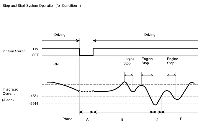
- Integrated Current Condition 1(for 1NR-FE with CVT and 1ND-TV):
When Status of Battery Charge Control are Change Control Condition Mode or Low Temperature Mode:
-
Phase A:
When the ignition switch is turned off, the integrated current value is recorded in the ECU memory. The value is carried over to the next trip.
-
Phase B:
Stop and start system control is permitted until the integrated current decreases to -5544 A-sec.
-
Phase C:
After the integrated current value decreases below -5544 A-sec, Stop and start system control is prohibited until the value increases to -4554 A-sec or more again. (The battery is being charged during this phase.)
-
Phase D:
Stop and start system control is permitted until the integrated current decreases to -5544 A-sec.
Stop and Start System Operation (for Condition 1)
-
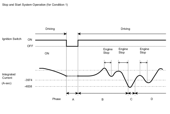
- Integrated Current Condition 1 (for 1NR-FE with Manual Transaxle and 1KR-FE):
When Status of Battery Charge Control are Change Control Condition Mode or Low Temperature Mode:
-
Phase A:
When the ignition switch is turned off, the integrated current value is recorded in the ECU memory. The value is carried over to the next trip.
-
Phase B:
Stop and start system control is permitted until the integrated current decreases to -4838 A-sec.
-
Phase C:
After the integrated current value decreases below -4838 A-sec, Stop and start system control is prohibited until the value increases to -3974 A-sec or more again. (The battery is being charged during this phase.)
-
Phase D:
Stop and start system control is permitted until the integrated current decreases to -4838 A-sec.
Stop and Start System Operation (for Condition 1)
-
- Integrated Current Condition 2 (for 1NR-FE with CVT and 1ND-TV):
When Status of Battery Charge Control is Stop and Start Standalone Mode, Stop and Start Restriction Mode or Temperature High/Low Mode:

*: The integrated current increases slowly due to low battery charge acceptance at low temperature.
-
Phase A:
When the ignition switch is turned off, the integrated current value is recorded in the ECU memory. The value is carried over to the next trip.
-
Phase B:
After engine start by ignition switch operation, Stop and start system control is prohibited until the integrated current reaches 0 A-sec once. (The battery is being charged during this phase.)
-
Phase C:
Stop and start system control is permitted until the integrated current decreases to -990 A-sec.
-
Phase D:
After the integrated current value decreases below -990 A-sec, Stop and start system control is prohibited until the value increase to 0 A-sec or more again. (The battery is being charged during this phase.)
-
Phase E:
Stop and start system control is permitted until the integrated current decreases to -990 A-sec.
Stop and Start System Operation (for Condition 2)
-
- Integrated Current Condition 2 (for 1NR-FE with Manual Transaxle and 1KR-FE):
When Status of Battery Charge Control is Stop and Start Standalone Mode, Stop and Start Restriction Mode or Temperature High/Low Mode:
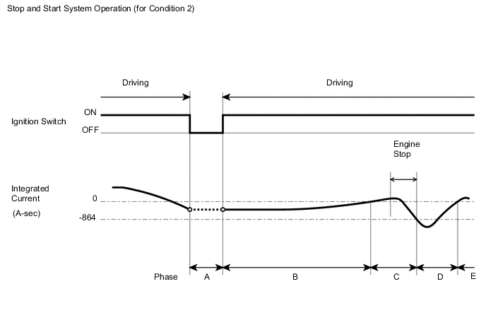
*: The integrated current increases slowly due to low battery charge acceptance at low temperature.
-
Phase A:
When the ignition switch is turned off, the integrated current value is recorded in the ECU memory. The value is carried over to the next trip.
-
Phase B:
After engine start by ignition switch operation, Stop and start system control is prohibited until the integrated current reaches 0 A-sec once. (The battery is being charged during this phase.)
-
Phase C:
Stop and start system control is permitted until the integrated current decreases to -864 A-sec.
-
Phase D:
After the integrated current value decreases below -864 A-sec, Stop and start system control is prohibited until the value increase to 0 A-sec or more again. (The battery is being charged during this phase.)
-
Phase E:
Stop and start system control is permitted until the integrated current decreases to -864 A-sec.
Stop and Start System Operation (for Condition 2)
-
Tech Tips
-
Performance (internal resistance) of lead-acid batteries used in typical vehicles changes according to the battery temperature. The internal resistance of the battery tends to be higher when the battery temperature is low. Thus, the Stop and start system switches the threshold for determining the power charge according to the battery temperature when performing stop and start control.
-
If the battery is deteriorated, the internal resistance has also increased and the stop and start rate becomes lower. (The total of idling time while the vehicle is stopped increases.)
-
When troubleshooting, if the malfunction cannot be identified, the battery might be deteriorated.
-
-
ACTIVE TEST
Tech Tips
Using the GTS to perform Active Tests allows relays, actuators and other items to be operated without removing any parts. This non-intrusive functional inspection can be very useful because intermittent operation may be discovered before parts or wiring is disturbed. Performing Active Tests early in troubleshooting is one way to save diagnostic time. Data List information can be displayed while performing Active Tests.
-
Connect the GTS to the DLC3.
-
Start the engine.
-
Turn the GTS on.
-
Enter the following menus: Powertrain / Stop and Start / Active Test.
-
Perform the Active Test by referring to the table below.
Stop and Start System Tester Display Test Part Control Range Diagnostic Note Buzzer Buzzer activation ON/OFF - Starter Starter activation ON/OFF Note
-
Maximum activation time is 3 seconds
-
After activation, operation is prohibited for 5 seconds
Pinion Gear Plunger*1 Pinion activation ON/OFF Note
-
Maximum activation time is 3 seconds
-
After activation, operation is prohibited for 5 seconds
Starter Motor Drive Magnet Switch*1 Starter motor activation ON/OFF Note
-
Maximum activation time is 3 seconds
-
After activation, operation is prohibited for 5 seconds
Permit Cond (A/C) A/C ON/OFF - Permit Cond (Battery) Battery ON/OFF - Permit Cond (Engine) Engine ON/OFF - Permit Cond (ABS)*1 ABS/VSC ON/OFF - AT Oil Pump (Hi)*1 AT oil pump activation ON/OFF HI activation AT Oil Pump (Lo)*1 AT oil pump activation ON/OFF LO activation Precondition (Control) Precondition (Control) activation ON/OFF Condition of permission or prohibition for terms listed below.
(ECM1, ECM2, idling, battery, ABS/VSC, ABS/VSC2, IGSW, DTC, A/C, interval, after running, engine hood closed, D door closed, cancel switch, interval for starter, key operation, AT/CVT, AT/CVT2, driver side buckle SW, ambient temperature)
Precondition2 (Control) Precondition2 (Control) activation ON/OFF Condition of permission or prohibition for terms listed below.
(idling, brake negative pressure, steering, road surface gradient, no shift operation, O/P check, starter check complete)
Start Cond (Hood Crtsy) Engine hood ON/OFF -
-
*1: for CVT
Tech Tips
Even if Stop and start system control is prohibited due to the condition of any of the systems listed above, performing the Active Tests allows Stop and start system control to be performed.
-