LANE DEPARTURE ALERT SYSTEM Power Source Circuit
WIRING DIAGRAM
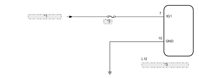
| *1 | from IG1 NO. 1 Relay |
| *2 | GAUGE |
| *3 | Pre-crash Safety City Sensor |
CAUTION / NOTICE / HINT
Note
-
Inspect the fuses for circuits related to this system before performing the following procedure.
-
When replacing the pre-crash safety city sensor, replace it with a new one and be sure to initialize the settings. If a pre-crash safety city sensor which was installed to another vehicle is used, the information stored in the pre-crash safety city sensor will not match the information from the vehicle and, as a result, a DTC may be stored.
-
If the pre-crash safety city sensor has been replaced, or the windshield glass has been replaced or removed/installed, be sure to perform Recognition Camera/Target Position Memory and Recognition Camera Axis Adjust.
-
Perform adjustment using "ONE TIME RECOGNITION" or "SEQUENTIAL RECOGNITION".
-
ONE TIME RECOGNITION
-
SEQUENTIAL RECOGNITION
PROCEDURE
-
INSPECT BATTERY VOLTAGE
-
Measure the battery voltage.
Standard voltage 11 to 14 V -
Using the parts location and system diagram, check the system for blown-out fuses, open or short circuits in the wire harness(es) and connectors that are not properly connected by performing a visual check.
Tech Tips
If the voltage is 11 V or less, replace or recharge the battery before proceeding to the next step.
NEXT 
-
-
CHECK PRE-CRASH SAFETY SENSOR
-
Check pre-crash safety city sensor.
Note
DTCs may be output when connectors are disconnected during inspection. Therefore, make sure to clear the DTCs using the GTS once the inspection has been completed.
-
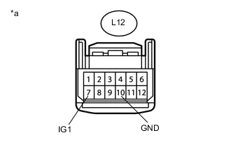
Text in Illustration *a Front view of wire harness connector
(to Pre-crash Safety City Sensor)
Disconnect the pre-crash safety city sensor connector.
-
Measure the voltage according to the value(s) in the table below.
Standard Voltage Tester Connection Switch Condition Specified Condition L12-7 (IG1) - Body ground Ignition switch ON (IG) 11 to 14 V L12-7 (IG1) - Body ground Ignition switch off Below 1 V -
Measure the resistance according to the value(s) in the table below.
Standard Resistance Tester Connection Condition Specified Condition L12-10 (GND) - Body ground Always Below 1 Ω
-
NG 
REPAIR OR REPLACE HARNESS OR CONNECTOR
OK
-
-
CHECK CAN COMMUNICATION SYSTEM
-
Use the GTS to check if the CAN communication system is functioning normally.
Result Result Proceed to CAN communication system DTCs are not output A CAN communication system DTCs are output B
A
PROCEED TO NEXT SUSPECTED AREA SHOWN IN PROBLEM SYMPTOMS TABLE Click here
B
GO TO CAN COMMUNICATION SYSTEM Click here
-