LANE DEPARTURE ALERT SYSTEM TERMINALS OF ECU
-
CHECK PRE-CRASH SAFETY CITY SENSOR

-
Disconnect the L12 pre-crash safety city sensor connector.
Note
-
DTCs may be output when connectors are disconnected during inspection. Therefore, be sure to clear the DTCs using the GTS once the inspection has been completed.
-
If a load of more than 10 kg (22 lb) is placed on the connector, it may break. Do not place more load than is necessary on the connector.
-
-
Measure the voltage and resistance according to the value(s) in the table below.
Terminal No. (Symbol) Wiring Color Terminal Description Condition Specified Condition L12-3 (LDSW) - Body ground P - Body ground Resistance Lane departure switch being pressed Below 1 Ω L12-3 (LDSW) - Body ground P - Body ground Resistance Lane departure switch not being pressed 10 kΩ or higher L12-7 (IG1) - Body ground LG - Body ground Voltage Ignition switch ON (IG) 11 to 14 V L12-7 (IG1) - Body ground LG - Body ground Voltage Ignition switch off Below 1 V L12-10 (GND) ←→ Body ground W-B - Body ground Resistance Always Below 1 Ω -
Reconnect the L12 pre-crash safety city sensor connector.
-
Check for pulses according to the value(s) in the table below.
Terminal No. (Symbol) Wiring Color Terminal Description Condition Specified Condition L12-5 (CA1P) - Body ground R - Body ground CAN communication signal Ignition switch ON (IG) Pulse generation (Refer to waveform 1) L12-11 (CA1N) - Body ground W - Body ground CAN communication signal Ignition switch ON (IG) Pulse generation (Refer to waveform 1) Tech Tips
If the result is not as specified, there is a CAN bus line, terminating resistor circuit (or product with this circuit) or pre-crash safety city sensor malfunction.
-
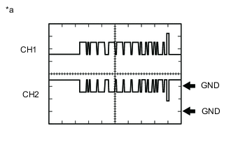
Text in Illustration *a waveform 1 Reference (Oscilloscope waveform)
Measurement Condition Item Content Measurement Terminal
-
CH1: L12-5 (CA1P) - Body ground
-
CH2: L12-11 (CA1N) - Body ground
Measurement Setting 1 V/DIV., 50 μsec./DIV. Condition Ignition switch ON (IG) -
-