CLUTCH SWITCH(for RHD) INSTALLATION
CAUTION / NOTICE / HINT
CAUTION:
Some of these service operations affect the SRS airbag system. Read the precautionary notices concerning the SRS airbag system before servicing (See page SUPPLEMENTAL RESTRAINT SYSTEMS > AIRBAG SYSTEM (w/ VSC) > PRECAUTION).
PROCEDURE
-
INSTALL NO. 2 CLUTCH START SWITCH ASSEMBLY
-
Install the No. 2 clutch start switch assembly with the nut.
- Torque:
- 16 N*m { 160 kgf*cm, 12 ft.*lbf }
-
Connect the connector.
-
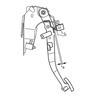
Text in Illustration *a Clearance Without depressing the clutch pedal, check that the clearance shown in the illustration is as specified.
Standard clearance Type Clearance for TMC Made 2.5 to 5.5 mm (0.098 to 0.217 in.) for TMMF Made except 1ND-TV 1.3 to 4.3 mm (0.051 to 0.169 in.) for TMMF Made 1ND-TV 0.5 to 3.5 mm (0.020 to 0.138 in.)
-
-
INSTALL LOWER NO. 1 INSTRUMENT PANEL AIRBAG ASSEMBLY (w/ Knee Airbag)
-
INSTALL LOWER INSTRUMENT PANEL FINISH PANEL (w/o Knee Airbag)
-
INSTALL NO. 1 INSTRUMENT PANEL UNDER COVER SUB-ASSEMBLY
-
CONNECT CABLE TO NEGATIVE BATTERY TERMINAL
- Torque:
- 5.4 N*m { 55 kgf*cm, 48 in.*lbf }
-
INSPECT SRS WARNING LIGHT
(See page SUPPLEMENTAL RESTRAINT SYSTEMS > AIRBAG SYSTEM (w/ VSC) > DIAGNOSIS SYSTEM)