CRUISE CONTROL SYSTEM(for Diesel) Clutch Switch Circuit
DESCRIPTION
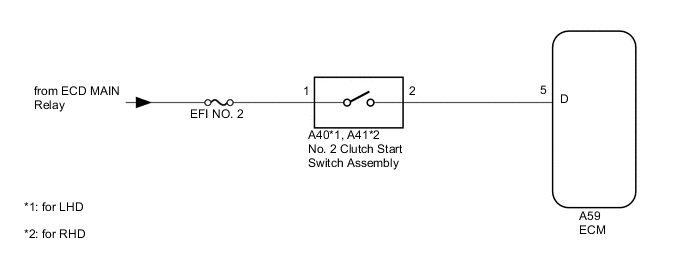
While depressing the clutch pedal, the clutch switch sends a signal to terminal 5 (D) of the ECM. The ECM cancels cruise control when terminal 5 (D) receives the signal.
WIRING DIAGRAM
CAUTION / NOTICE / HINT
Note
-
Inspect the fuses for circuits related to this system before performing the following inspection procedure.
-
First perform the communication function inspections in How to Proceed with Troubleshooting to confirm that there are no CAN communication malfunctions before troubleshooting this problem.
PROCEDURE
-
INSPECT NO. 2 CLUTCH START SWITCH ASSEMBLY
-
Inspect the No. 2 clutch start switch assembly.
Result Result Proceed to OK A NG (for LHD) B NG (for RHD) C
B 
REPLACE NO. 2 CLUTCH START SWITCH ASSEMBLY Click here
C
REPLACE NO. 2 CLUTCH START SWITCH ASSEMBLY Click here
A 
-
-
CHECK HARNESS AND CONNECTOR (NO. 2 CLUTCH START SWITCH ASSEMBLY - ECM AND BATTERY)
-
Disconnect the A40*1 or A41*2 No. 2 clutch start switch assembly connector.
-
*1: for LHD
-
*2: for RHD
-
-
Disconnect the A59 ECM connector.
-
Measure the voltage according to the value(s) in the table below.
Standard Voltage for LHD Tester Connection Switch Condition Specified Condition A40-1 - Body ground Ignition switch ON 11 to 14 V Ignition switch off Below 1 V for RHD Tester Connection Switch Condition Specified Condition A41-1 - Body ground Ignition switch ON 11 to 14 V Ignition switch off Below 1 V -
Measure the resistance according to the value(s) in the table below.
Standard Resistance for LHD Tester Connection Condition Specified Condition A40-2 - A59-5 (D) Always Below 1 Ω A40-2 - Body ground Always 10 kΩ or higher for RHD Tester Connection Condition Specified Condition A41-2 - A59-5 (D) Always Below 1 Ω A41-2 - Body ground Always 10 kΩ or higher
OK
PROCEED TO NEXT SUSPECTED AREA SHOWN IN PROBLEM SYMPTOMS TABLE Click here
NG
REPAIR OR REPLACE HARNESS OR CONNECTOR
-