CRUISE CONTROL SYSTEM(for Diesel), Diagnostic DTC:P0571
| DTC Code | DTC Name |
|---|---|
| P0571 | Stop Light Switch Circuit Malfunction |
DESCRIPTION
When the brake pedal is depressed, the stop light switch sends a signal to the ECM. Upon receiving the signal, the ECM cancels cruise control. Even if there is a malfunction in the stop light signal circuit while cruise control is in operation, normal driving is maintained due to a fail-safe function.
When the brake pedal is depressed, positive voltage is applied to terminal STP of the ECM through the STOP fuse and stop light switch, and the ECM cancels cruise control.
| DTC Code | DTC Detection Condition | Trouble Area |
|---|---|---|
| P0571 | The voltages of terminals ST1 - and STP of the ECM are both below 1 V for 0.5 seconds or more. |
|
WIRING DIAGRAM
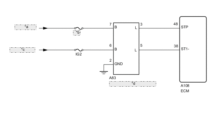
| *a | from Battery |
| *b | STOP |
| *c | from IG2 Relay |
| *d | Stop Light Switch Assembly |
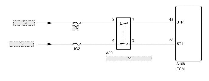
| *a | from Battery |
| *b | STOP |
| *c | from IG2 Relay |
| *d | Stop Light Switch Assembly |
CAUTION / NOTICE / HINT
Note
Inspect the fuses for circuits related to this system before performing the following inspection procedure.
PROCEDURE
-
WIRE HARNESS AND CONNECTOR (STOP LIGHT SWITCH POWER SOURCE)
-
for LED Type Stop Light
-
Disconnect the stop light switch assembly connector.
-
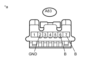
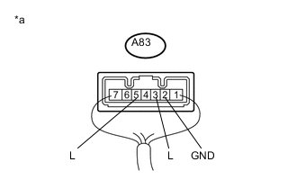
Text in Illustration *a Front view of wire harness connector
(to Stop Light Switch Assembly)
Measure the voltage according to the value(s) in the table below.
Standard Voltage Tester Connection Switch Condition Specified Condition A83-7 (B) - A83-2 (GND) Always 11 to 14 V A83-6 (B) - A83-2 (GND) Ignition switch ON 11 to 14 V -
Measure the resistance according to the value(s) in the table below.
Standard Resistance Tester Connection Condition Specified Condition A83-2 (GND) - Body ground Always Below 1 Ω
-
-
for Bulb Type Stop Light
-
Disconnect the stop light switch assembly connector.
-
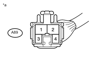
Text in Illustration *a Front view of wire harness connector
(to Stop Light Switch Assembly)
Measure the voltage according to the value(s) in the table below.
Standard Voltage Tester Connection Switch Condition Specified Condition A89-2 - Body ground Always 11 to 14 V A89-4 - Body ground Ignition switch ON 11 to 14 V
-
NG 
REPAIR OR REPLACE HARNESS OR CONNECTOR
OK 
-
-
INSPECT STOP LIGHT SWITCH ASSEMBLY
-
for LED Type Stop Light
-
Reconnect the stop light switch assembly connector.
-
Text in Illustration *a Component with harness connected
(Stop Light Switch Assembly)
Measure the voltage according to the value(s) in the table below.
Standard Voltage Tester Connection Switch Condition Specified Condition A83-3 (L) - A83-2 (GND) Ignition switch off,
Brake pedal not depressed
Below 1 V A83-3 (L) - A83-2 (GND) Ignition switch off,
Brake pedal depressed
11 to 14 V A83-5 (L) - A83-2 (GND) Ignition switch ON,
Brake pedal not depressed
11 to 14 V A83-5 (L) - A83-2 (GND) Ignition switch ON,
Brake pedal depressed
Below 1 V
-
-
for Bulb Type Stop Light
-
Remove the stop light switch assembly Click here.
-
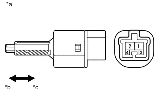
Text in Illustration *a Component with harness connected
(Stop Light Switch Assembly)
*b Not pushed *c Pushed Measure the resistance according to the value(s) in the table below.
Standard Resistance Tester Connection Switch Condition Specified Condition 1 - 2 Switch pin not pushed Below 1 Ω 3 - 4 Switch pin not pushed 10 kΩ or higher 1 - 2 Switch pin pushed 10 kΩ or higher 3 - 4 Switch pin pushed Below 1 Ω
-
NG
REPLACE STOP LIGHT SWITCH ASSEMBLY Click here
OK
-
-
CHECK HARNESS AND CONNECTOR (ECM - STOP LIGHT SWITCH ASSEMBLY)
-
for LED Type Stop Light
-
Disconnect the A83 stop light switch assembly connector.
-
Disconnect the A108 ECM connector.
-
Measure the resistance according to the value(s) in the table below.
Standard Resistance Tester Connection Condition Specified Condition A108-48 (STP) - A83-3 (L) Always Below 1 Ω A108-38 (ST1-) - A83-5 (L) Always Below 1 Ω A108-48 (STP) or A83-3 (L) - Body ground Always 10 kΩ or higher A108-38 (ST1-) or A83-5 (L) - Body ground Always 10 kΩ or higher
-
-
for Bulb Type Stop Light
-
Disconnect the A89 stop light switch assembly connector.
-
Disconnect the A108 ECM connector.
-
Measure the resistance according to the value(s) in the table below.
Standard Resistance Tester Connection Condition Specified Condition A108-38 (ST1-) - A89-3 Always Below 1 Ω A108-48 (STP) - A89-1 Always Below 1 Ω A108-38 (ST1-) or A89-3 - Body ground Always 10 kΩ or higher A108-48 (STP) or A89-1 - Body ground Always 10 kΩ or higher
-
OK
REPLACE ECM Click here
NG
REPAIR OR REPLACE HARNESS OR CONNECTOR
-