CRUISE CONTROL SYSTEM(for Diesel) TERMINALS OF ECU
-
CHECK DRIVING SUPPORT ECU ASSEMBLY

Terminal No. (Symbol) Wiring Color Terminal Description Condition Specified Condition F121-30 (B) - F121-25 (GND) LG - W-B Battery Always 11 to 14 V F121-28 (ST1-) - F121-25 (GND) R - W-B Stop light switch signal Ignition switch ON, Brake pedal released 11 to 14 V F121-28 (ST1-) - F121-25 (GND) R - W-B Stop light switch signal Ignition switch ON, Brake pedal depressed Below 1 V F121-27 (STP-) - F121-25 (GND) G - W-B Stop light switch signal Brake pedal released Below 1 V F121-27 (STP-) - F121-25 (GND) G - W-B Stop light switch signal Brake pedal depressed 11 to 14 V F121-25 (GND) - Body ground W-B - Body ground Earth (ground) circuit of driving support ECU assembly Always Below 1 Ω F121-23 (CCS) - F121-25 (GND) G - W-B Cruise control switch circuit Ignition switch ON 1 MΩ or higher F121-23 (CCS) - F121-25 (GND) G - W-B Cruise control switch circuit Ignition switch ON, Cruise control switch on Below 2.5 Ω F121-23 (CCS) - F121-25 (GND) G - W-B Cruise control switch circuit Ignition switch ON, +RES switch on 235 to 245 Ω F121-23 (CCS) - F121-25 (GND) G - W-B Cruise control switch circuit Ignition switch ON, -SET switch on 617 to 643 Ω F121-23 (CCS) - F121-25 (GND) G - W-B Cruise control switch circuit Ignition switch ON, CANCEL switch on 1509 to 1571 Ω F121-17 (CA2L) - F121-25 (GND) W - W-B CAN communication line Ignition switch ON Pulse generation
(see waveform 1)
F121-39 (CA2H) - F121-25 (GND) R - W-B CAN communication line Ignition switch ON Pulse generation
(see waveform 2)
-
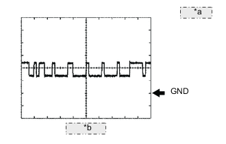
*a 1 V/DIV. *b 10 μs/DIV. WAVEFORM 1
-
CAN communication signal
Driving Support ECU Assembly Terminal Name CA2L and GND Tester Range 1 V/DIV., 10 μsec./DIV. Condition Ignition switch ON Tech Tips
The waveform varies depending on the CAN communication signal.
-
-
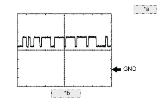
*a 1 V/DIV. *b 10 μs/DIV. WAVEFORM 2
-
CAN communication signal
Driving Support ECU Assembly Terminal Name CA2H and GND Tester Range 1 V/DIV., 10 μsec./DIV. Condition Ignition switch ON Tech Tips
The waveform varies depending on the CAN communication signal.
-
-
-
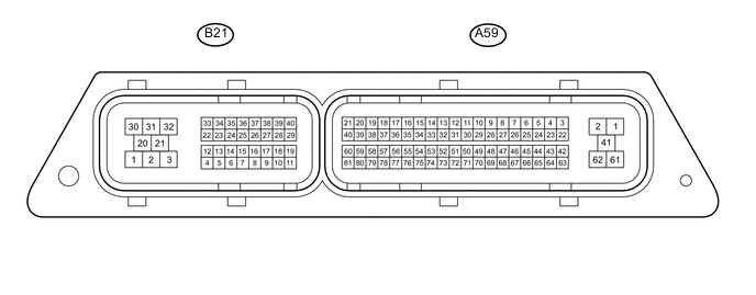
TERMINALS OF ECM
Tech Tips
The standard normal voltage between each pair of ECM terminals is shown in the table below. The appropriate conditions for checking each pair of terminals are also indicated.
The result of the checks should be compared with the standard normal voltage for that pair of terminals, which is displayed in the Specified Condition column.
The illustration above can be used as a reference to identify the ECM terminal locations.
Terminal No. (Symbol) Wiring Color Terminal Description Condition Specified Condition A59-1 (+B) - A59-2 (E1) B - W-B Power source of ECM Ignition switch ON 11 to 14 V A59-61 (+B2) - A59-2 (E1) B - W-B Power source of ECM Ignition switch ON 11 to 14 V A59-23 (BATT) - A59-2 (E1) V - W-B Battery (for measuring the battery voltage and for the ECM memory) Always 11 to 14 V A59-7 (IGSW) - A59-2 (E1) R - W-B Ignition switch Ignition switch ON 11 to 14 V A59-55 (VPA) - A59-57 (EPA) R - R Accelerator pedal sensor assembly (for engine control) Ignition switch ON
Accelerator pedal fully released
0.6 to 1.0 V Ignition switch ON
Accelerator pedal fully depressed
3.0 to 4.6 V A59-52 (VPA2) - A59-54 (EPA2) L - B Accelerator pedal sensor assembly (for sensor malfunction detection) Ignition switch ON
Accelerator pedal fully released
1.4 to 1.8 V Ignition switch ON
Accelerator pedal fully depressed
3.7 to 5.0 V A59-56 (VCPA) - A59-57 (EPA) B - R Power source of accelerator pedal sensor assembly (for VPA) Ignition switch ON 4.5 to 5.0 V A59-53 (VCP2) - A59-54 (EPA2) W - B Power source of accelerator pedal sensor assembly (for VPA2) Ignition switch ON 4.5 to 5.0 V B21-1 (IJ1+) - B21-21 (IJ1-) B - W Injector Idling Pulse generation B21-2 (IJ2+) - B21-30 (IJ2-) R - W Injector Idling Pulse generation B21-3 (IJ3+) - B21-31 (IJ3-) L - Y Injector Idling Pulse generation B21-20 (IJ4+) - B21-32 (IJ4-) G - B Injector Idling Pulse generation A59-3 (CANH) - A59-2 (E1) L - W-B CAN communication line Ignition switch ON Pulse generation
(See waveform 1)
A59-4 (CANL) - A59-2 (E1) W - W-B CAN communication line Ignition switch ON Pulse generation
(See waveform 2)
A59-17 (CANP) - A59-2 (E1) B - W-B CAN communication line Ignition switch ON Pulse generation
(See waveform 1)
A59-16 (CANN) - A59-2 (E1) W - W-B CAN communication line Ignition switch ON Pulse generation
(See waveform 2)
-
*a 1 V/DIV. *b 10 μs/DIV. WAVEFORM 1
-
CAN communication signal
ECM Terminal Name CANH and E1
CANP and E1
Tester Range 1 V/DIV., 10 μs/DIV. Condition Engine stopped, ignition switch ON Tech Tips
The waveform varies depending on the CAN communication signal.
-
-
*a 1 V/DIV. *b 10 μs/DIV. WAVEFORM 2
-
CAN communication signal
ECM Terminal Name CANL and E1
CANN and E1
Tester Range 1 V/DIV., 10 μs/DIV. Condition Engine stopped, ignition switch ON Tech Tips
The waveform varies depending on the CAN communication signal.
-
-