SPEED LIMITER SYSTEM TERMINALS OF ECM
-
CHECK ECM
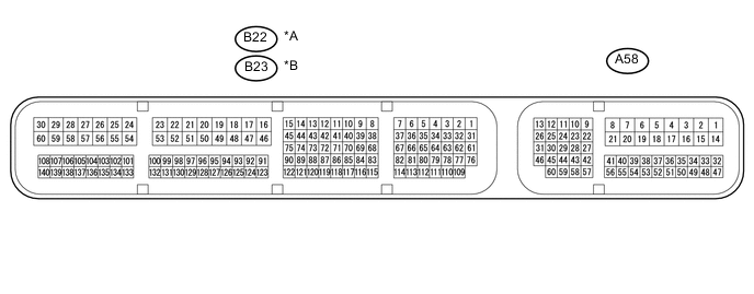
Text in Illustration *A for LHD *B for RHD
-
Disconnect the B22*1 or B23*2 and A58 ECM connectors.
-
*1: for LHD
-
*2: for RHD
-
-
Measure the voltage and resistance according to the value(s) in the table below.
Terminal No. (Symbol) Wiring Color Terminal Description Condition Specified Condition A58-1 (BATT) - Body ground Y - Body ground Power source circuit Always 11 to 14 V A58-37 (IGSW) - Body ground R - Body ground IG power source circuit Ignition switch ON 11 to 14 V Ignition switch off Below 1 V A58-40 (ASLM) - Body ground GR - Body ground Speed limiter main switch signal Speed limiter main switch on Below 1 Ω Speed limiter main switch off 10 kΩ or higher B22-16 (E1) - Body ground*1 W-B - Body ground Ground Always Below 1 Ω B23-16 (E1) - Body ground*2 W-B - Body ground Ground Always Below 1 Ω
-
*1: for LHD
-
*2: for RHD
-
-