STARTER(for Cold Area Specification Vehicles) REASSEMBLY
CAUTION / NOTICE / HINT
Tech Tips
Use high-temperature grease to lubricate the bearings, gears and return spring when assembling the starter assembly.
PROCEDURE
-
INSTALL STARTER CENTER BEARING CLUTCH SUB-ASSEMBLY
-
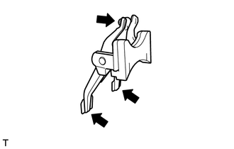
Apply high-temperature grease to the starter drive lever set pin as shown in the illustration.
Text in Illustration 
High-temperature Grease -
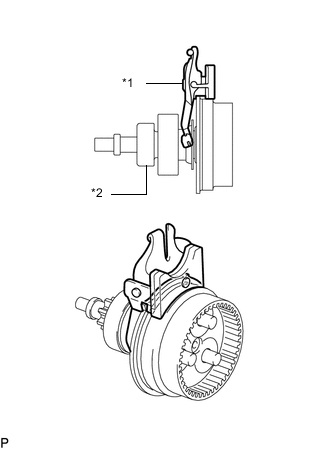
Text in Illustration *1 Starter Drive Lever Set Pin *2 Starter Center Bearing Clutch Sub-assembly Install the starter drive lever set pin to the starter center bearing clutch sub-assembly.
-
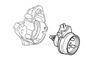
Install the starter center bearing clutch sub-assembly together with the starter drive lever set pin to the starter drive housing assembly.
-
-
INSTALL PLANETARY GEAR
-
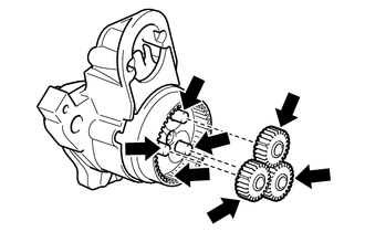
Apply high-temperature grease to the planetary gears and pin parts of the starter center bearing clutch sub-assembly.
Text in Illustration High-temperature Grease -
Install the 3 planetary gears to the pins of the planetary shaft.
-
-
INSTALL STARTER ARMATURE ASSEMBLY
-
Hold the starter commutator end frame assembly in a vise between aluminum plates.
Note
-
Do not overtighten the vise.
-
Do not drop the starter armature assembly.
-
-
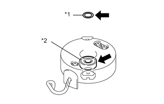
Text in Illustration *1 Plate Washer *2 Bearing High-temperature Grease Apply high-temperature grease to the plate washer and bearing.
-
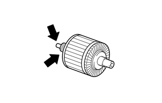
Apply high-temperature grease to the starter armature assembly as shown in the illustration.
Text in Illustration High-temperature Grease -
Install the starter armature assembly to the starter commutator end frame assembly.
-
Install the plate washer to the starter armature shaft.
-
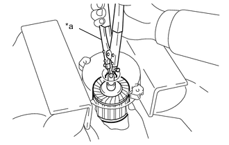
Text in Illustration *1 Snap Ring Pliers Using snap ring pliers, install a new snap ring.
Note
-
Be sure to install the snap ring in the armature shaft groove securely.
-
Be sure to properly install the snap ring because it easily expands.
-
-
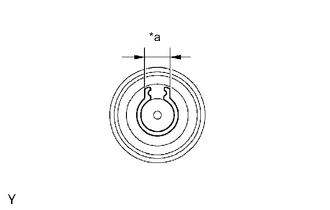
Text in Illustration *a Length Check the snap ring length.
-
Using a vernier caliper, measure the snap ring length.
Maximum length 5.0 mm (0.197 in.) If the length is more than the maximum, replace the snap ring.
-
-
-
INSTALL STARTER COMMUTATOR END FRAME COVER
-
Install the starter commutator end frame cover to the starter commutator end frame assembly.
-
-
INSTALL STARTER ARMATURE PLATE
-
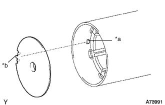
Text in Illustration *a Key *b Keyway Align the keyway of the starter armature plate with the key inside the starter yoke assembly, and install the starter armature plate.
-
-
INSTALL STARTER COMMUTATOR END FRAME ASSEMBLY
-

Text in Illustration *a Rubber Part *b Groove Align the rubber part on the starter commutator end frame assembly with the groove of the starter yoke assembly.
-
Install the starter commutator end frame assembly to the starter yoke assembly.
Note
The magnet of the starter yoke assembly may attract the starter armature assembly when the starter commutator end frame assembly is installed, causing the magnet to break.
-
-
INSTALL STARTER YOKE ASSEMBLY
-
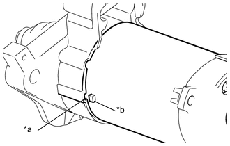
Text in Illustration *a Groove *b Claw Align the claw of the starter yoke assembly with the groove inside the starter drive housing assembly.
-
Install the starter yoke assembly with the 2 through bolts.
- Torque:
- 6.0 N*m { 61 kgf*cm, 53 in.*lbf }
-
-
INSTALL REPAIR SERVICE STARTER KIT
-
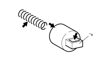
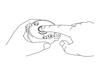
Text in Illustration *a Hook High-temperature Grease Apply high-temperature grease to the plunger and return spring.
-
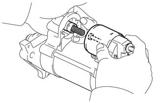
Hang the plunger hook of the repair service starter kit on the starter drive lever set pin.
-
Install the plunger and return spring.
-
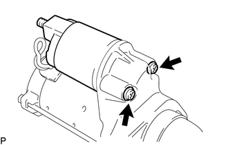
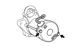
Install the repair service starter kit with the 2 screws.
- Torque:
- 7.5 N*m { 76 kgf*cm, 66 in.*lbf }
-
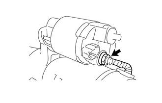
Connect the lead wire to terminal C with the nut.
- Torque:
- 10 N*m { 102 kgf*cm, 7 ft.*lbf }
-