STARTER(for Transaxle CVT with Stop and Start System) REASSEMBLY
PROCEDURE
-
INSTALL STARTER CENTER BEARING CLUTCH SUB-ASSEMBLY
-
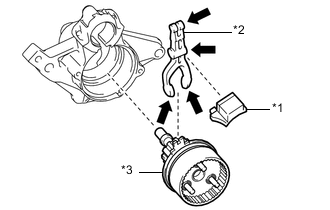
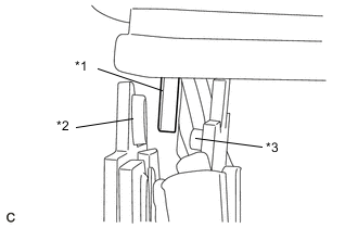
*1 Rubber Seal *2 Pinion Drive Lever *3 Starter Center Bearing Clutch Sub-assembly 
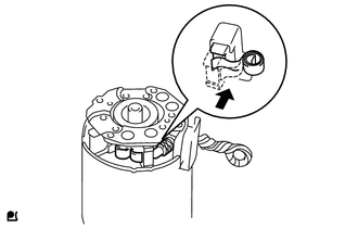
High-temperature Grease Apply high-temperature grease to the pinion drive lever as shown in the illustration.
-
Install the pinion drive lever and rubber seal to the starter center bearing clutch sub-assembly.
-
Install the starter center bearing clutch sub-assembly together with pinion drive lever and rubber seal to the starter drive housing assembly.
-
-
INSTALL PLANETARY GEAR
-
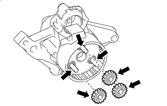
High-temperature Grease Apply high-temperature grease to the 3 planetary gears, 3 planetary gear shafts and starter center bearing clutch sub-assembly.
-
Install the 3 planetary gears to the starter center bearing clutch sub-assembly.
-
-
INSTALL STARTER ARMATURE ASSEMBLY
-
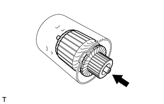
Install the starter armature assembly to the starter yoke assembly.
-
-
INSTALL STARTER BRUSH HOLDER ASSEMBLY
-
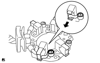
Hold the brush spring back and install the 4 brushes to the starter brush holder assembly.
-
Install the starter brush holder assembly to the starter armature assembly and push in the 4 brushes.
-
*1 Grommet *2 Negative (-) Brush Holder Plate *3 Positive (+) Motor Lead Wire Fit the protrusion of the grommet between the negative (-) brush holder plate and positive (+) motor lead wire.
-
-
INSTALL STARTER COMMUTATOR END FRAME ASSEMBLY
-
*1 Lead Wire Rubber Install the starter commutator end frame assembly to the starter yoke assembly.
Note
Align the lead wire rubber of the starter yoke assembly with the cutout of the starter commutator end frame assembly.
-
Install the 2 screws.
- Torque:
- 1.5 N*m { 15 kgf*cm, 13 in.*lbf }
-
-
INSTALL STARTER ARMATURE PLATE
-
*a Stopper *b Protrusion Align the starter armature plate so that the protrusion fits between the stoppers of the starter yoke assembly, and install the starter armature plate.
Note
Make sure the protrusion of the starter armature plate is inserted between the stoppers of the starter yoke assembly.
-
-
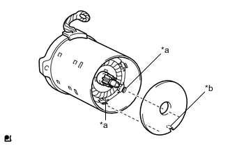
INSTALL STARTER YOKE ASSEMBLY
-
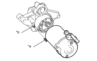
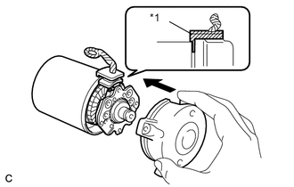
*a Protrusion *b Cutout Install the starter yoke assembly to the starter drive housing assembly.
Note
Align the cutout of the starter yoke assembly with the protrusion of the starter drive housing assembly.
-
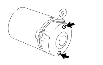
Using a T25 "TORX" socket wrench, install the 2 through bolts.
- Torque:
- 6.0 N*m { 61 kgf*cm, 53 in.*lbf }
-
-
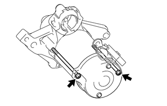
INSTALL REPAIR SERVICE STARTER KIT
-
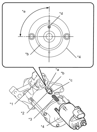
*1 Pinion Drive Lever *2 Plunger *3 Return Spring *4 Magnet Switch *a Hook *b Plunger Cover *c Protrusion *d Ventilation Hole *e 90° Hang the hook of the plunger on the pinion drive lever and install the repair service starter kit.
Note
-
Make sure the return spring is not resting on the protrusion of the plunger or pushed between the magnet switch and plunger.
-
Install the plunger cover so that the ventilation hole is positioned as shown in the illustration.
-
-
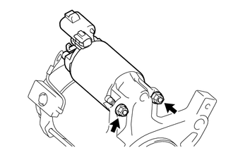
Install the 2 nuts.
- Torque:
- 7.5 N*m { 76 kgf*cm, 66 in.*lbf }
-
-
INSTALL WIRE HARNESS
-
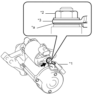
*1 Condenser *2 Nut *3 Wire Harness *a Condenser Terminal Install the condenser terminal and wire harness to the repair service starter kit with the nut.
- Torque:
- 10 N*m { 102 kgf*cm, 89 in.*lbf }
Note
Make sure to install the condenser terminal and wire harness in the correct order and in the correct direction.
-