STARTER(for Cold Area) INSPECTION
PROCEDURE
-
INSPECT STARTER ASSEMBLY
Note
The following tests must be performed within 5 seconds to prevent the coil from burning out.
-
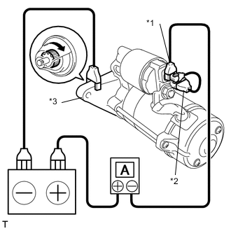
Perform a pull-in test.
-
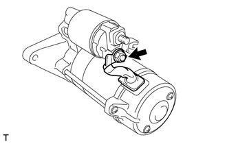
Remove the nut and disconnect the motor lead wire from terminal C.
-
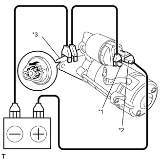
Text in Illustration *1 Terminal C *2 Terminal 50 *3 Body Connect the battery to the magnet starter switch as shown in the illustration. Check that the clutch pinion gear is extended.
If the clutch pinion gear does not move, replace the magnet starter switch assembly.
-
-
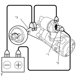
Text in Illustration *1 Terminal C *2 Terminal 50 *3 Body Perform a holding test.
-
Disconnect the negative (-) lead from terminal C. Check that the clutch pinion gear remains extended.
If the clutch pinion gear returns inward, replace the magnet starter switch assembly.
-
-
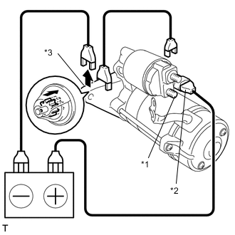
Text in Illustration *1 Terminal C *2 Terminal 50 *3 Body Inspect the clutch pinion gear return.
-
Disconnect the negative (-) lead from the switch body. Check that the clutch pinion gear returns.
If the clutch pinion gear does not return inward, replace the magnet starter switch assembly.
-
-
Perform a no-load performance test.
-
Connect the motor lead wire to terminal C. Make sure that the lead is not grounded.
- Torque:
- 6.5 N*m { 66 kgf*cm, 58 in.*lbf }
-
Clamp the starter in a vise.
Note
Do not clamp the vise to tightly.
-
Text in Illustration *1 Terminal 30 *2 Terminal 50 *3 Body Connect the battery and an ammeter to the starter as shown in the illustration.
-
Check that the starter rotates smoothly and steadily with the clutch pinion gear extended.
Measure the current according to the value(s) in the table below.
Standard Current Tester Connection Condition Specified Condition Battery positive terminal - Terminal 30 - Terminal 50 11.5 V Below 190 A If the result is not as specified, replace the starter assembly.
-
-
-
INSPECT MAGNET STARTER SWITCH ASSEMBLY
-
Check the plunger.
-
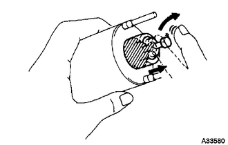
Push in the plunger and check that it returns quickly to its original position.
If necessary, replace the magnet starter switch assembly.
-
-
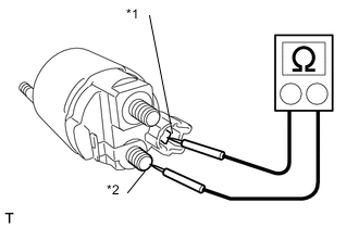
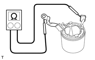
Text in Illustration *1 Terminal 50 *2 Terminal C Check the pull-in coil for an open circuit.
-
Measure the resistance according to the value(s) in the table below.
Standard Resistance Tester Connection Condition Specified Condition Terminal 50 - Terminal C Always Below 1 Ω If the result is not as specified, replace the magnet starter switch assembly.
-
-
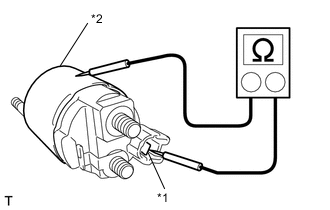
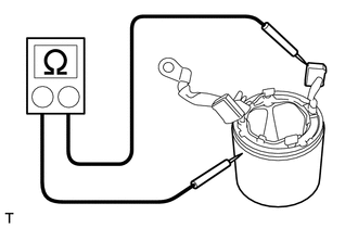
Text in Illustration *1 Terminal 50 *2 Switch Body Check the holding coil for an open circuit.
-
Measure the resistance according to the value(s) in the table below.
Standard Resistance Tester Connection Condition Specified Condition Terminal 50 - Switch body Always Below 2 Ω If the result is not as specified, replace the magnet starter switch assembly.
-
-
-
INSPECT STARTER ARMATURE ASSEMBLY
-
Check the commutator.
-
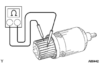
Measure the resistance according to the value(s) in the table below.
Standard Resistance Tester Connection Condition Specified Condition Segment - Segment Always Below 1 Ω If the result is not as specified, replace the starter armature assembly.
-
-
Check the commutator.
-
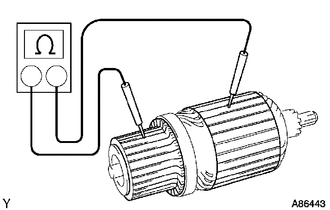
Measure the resistance according to the value(s) in the table below.
Standard Resistance Tester Connection Condition Specified Condition Commutator - Armature coil core Always 10 kΩ or higher If the result is not as specified, replace the starter armature assembly.
-
-
Check the commutator surface for dirt and burns.
If the surface is dirty or burnt, restore it with sandpaper (No. 400) or a lathe.
-
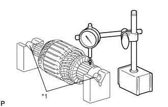
Text in Illustration *1 Armature shaft Check the commutator for circle runout.
-
Place the armature shaft on V-blocks.
-
Using a dial indicator, measure the circle runout.
Maximum runout 0.05 mm (0.00197 in.) If the runout is greater than the maximum, replace the starter armature assembly.
-
-
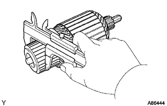
Using a vernier caliper, measure the commutator diameter.
Standard diameter 35.0 mm (1.378 in.) Minimum diameter 34.0 mm (1.339 in.) If the diameter is less than the minimum, replace the armature assembly.
-
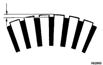
Check that the undercut portion between the segments is free of foreign matter and measure its depth.
Standard undercut depth 0.7 mm (0.0276 in.) Minimum undercut depth 0.2 mm (0.00787 in.) If the undercut depth is less than the minimum, adjust it with a hacksaw blade.
-
-
INSPECT STARTER YOKE ASSEMBLY
-
Measure the resistance according to the value(s) in the table below.
Standard Resistance Tester Connection Condition Specified Condition Lead wire - Brush Always Below 1 Ω If the result is not as specified, replace the starter yoke assembly.
-
Measure the resistance according to the value(s) in the table below.
Standard Resistance Tester Connection Condition Specified Condition Brush - Starter yoke body Always 10 kΩ or higher If the result is not as specified, replace the starter yoke assembly.
-
-
INSPECT BRUSH
-
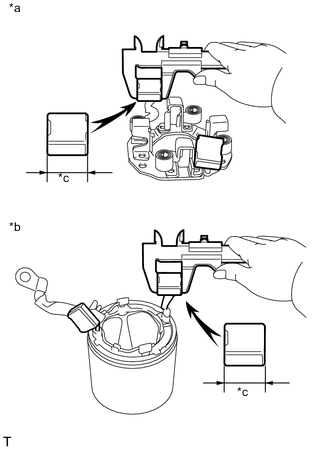
Text in Illustration *a Brush Holder Side *b Yoke Side *c Length Using a vernier caliper, measure the brush length.
Standard length 15 mm (0.591 in.) Minimum length 9.0 mm (0.354 in.) If the brush length is less than the minimum, replace the starter yoke assembly.
-
-
INSPECT STARTER BRUSH HOLDER ASSEMBLY
-
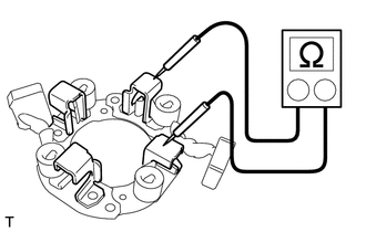
Measure the resistance according to the value(s) in the table below.
Standard Resistance Tester Connection Condition Specified Condition Positive brush holder - Negative brush holder Always 10 kΩ or higher If the result is not as specified, replace the starter brush holder assembly.
-
Inspect the load of the brush spring.
-
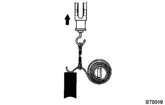
Take the pull scale reading immediately after the brush spring separates from the brush.
Standard spring installed load 21.5 to 27.5 N (2.2 to 2.8 kgf, 4.8 to 6.2 lbf) Minimum spring installed load 12.3 N (1.3 kgf, 2.8 lbf) If the installed load is less than the minimum, replace the brush holder.
-
-
-
INSPECT STARTER CENTER BEARING CLUTCH SUB-ASSEMBLY
-
Check the gear teeth of the planetary gear and starter center bearing clutch for wear or damage.
If any planetary gear is damaged, replace the planetary gear assembly.
If any gear of the starter center bearing clutch is damaged, replace the starter center bearing clutch sub-assembly.
-
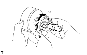
Text in Illustration *a Free *b Lock Check the movement of the clutch pinion gear.
-
Hold the starter clutch, rotate the clutch pinion gear clockwise, and check that it turns freely.
-
Try to rotate the clutch pinion gear counterclockwise and check that it locks.
If the clutch pinion gear cannot be turned clockwise smoothly, or does not lock in the counterclockwise direction, replace the starter center bearing clutch sub-assembly.
-
-