STARTER(for TMMF Made Cold Area Specification Vehicles) INSPECTION
PROCEDURE
-
INSPECT STARTER ASSEMBLY
Note
Perform each of the following tests within 3 to 5 seconds.
-
Perform pull-in test.
-
Disconnect the field coil lead wire from terminal C.
-
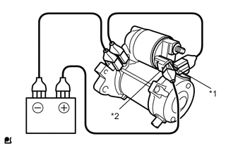
Text in Illustration *1 Terminal C *2 Terminal 50 Connect the battery to the starter magnetic switch as shown in the illustration and check that the pinion gear is extended.
-
-
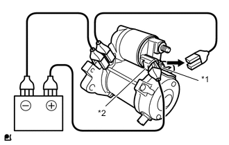
Text in Illustration *1 Terminal C *2 Terminal 50 Perform holding test.
-
Check that the pinion gear does not return inward after the cable of terminal C is disconnected.
-
-
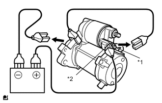
Text in Illustration *1 Terminal C *2 Terminal 50 Inspect the clutch pinion gear return.
-
Move the pinion gear toward the armature.
-
-
Perform the operation test without any load.
-
Connect the field coil lead wire to terminal C.
- Torque:
- 5.9 N*m { 60 kgf*cm, 52 in.*lbf }
-
Clamp the starter in a vise.
Note
Do not clamp the vise to tightly.
-
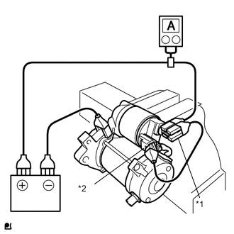
Text in Illustration *1 Terminal 30 *2 Terminal 50 Connect the battery and ammeter to the starter as shown in the illustration.
-
Check that the starter rotates smoothly and steadily with the clutch pinion gear extended. Measure the current according to the value(s) in the table below.
Standard Current Tester Connection Condition Specified Condition Battery positive terminal - Terminal 30 - Terminal 50 11.5 V Below 190 A If the result is not as specified, replace the starter assembly.
-
-
-
INSPECT MAGNET STARTER SWITCH ASSEMBLY
-
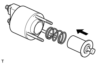
Check the plunger.
-
Install the plunger and spring onto the switch body.
-
Push in the plunger, then check that it returns quickly to its original position.
If necessary, replace the magnet starter switch assembly.
-
-
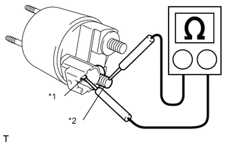
Text in Illustration *1 Terminal 50 *2 Terminal C Check the pull-in coil for an open circuit.
-
Measure the resistance according to the value(s) in the table below.
Standard Resistance Tester Connection Condition Specified Condition Terminal 50 - Terminal C Always Below 1 Ω If the standard is not met, replace the magnet starter switch assembly.
-
-
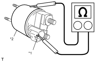
Text in Illustration *1 Terminal 50 *2 Switch Body Measure the resistance according to the value(s) in the table below.
-
Using an ohmmeter, measure the resistance between terminals 50 and the switch body.
Standard Resistance Tester Connection Condition Specified Condition Terminal 50 - Switch body Always Below 1.5 Ω If the standard is not met, replace the magnet starter switch assembly.
-
-
-
INSPECT STARTER ARMATURE ASSEMBLY
-
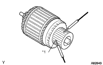
Text in Illustration *1 Commutator Check the commutator for an open circuit.
-
Measure the resistance according to the value(s) in the table below.
Standard Resistance Tester Connection Condition Specified Condition Segment - Segment Always Below 1 Ω If the standard is not met, replace the starter armature assembly.
-
-
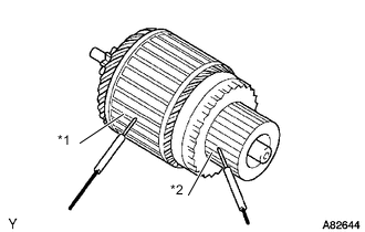
Text in Illustration *1 Armature *2 Commutator Check the commutator for ground.
-
Measure the resistance according to the value(s) in the table below.
Standard Resistance Tester Connection Condition Specified Condition Commutator - Armature coil core Always 10 kΩ or higher If the standard is not met, replace the starter armature assembly.
-
-
Check the appearance.
If the surface is dirty or burnt, restore the surface with 400-grit sandpaper on a lathe.
-
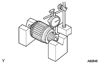
Check the commutator circuit for runout.
-
Place the commutator on V-blocks.
-
Using a dial indicator, measure the circle runout.
Standard runout 0.02 mm (0.0008 in.) Maximum runout 0.05 mm (0.0020 in.) If the runout is greater than the maximum, replace the armature assembly.
-
-
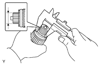
Using a vernier caliper, measure the commutator diameter.
Standard diameter 29 mm (1.142 in.) Minimum diameter 28 mm (1.102 in.) If the diameter is less than the minimum, replace the armature assembly.
-
-
INSPECT STARTER BRUSH HOLDER ASSEMBLY
-
Remove the claw of the spring, then remove the 4 brushes.
-
Using a vernier caliper, measure the brush length.
Standard length 15.5 mm (0.610 in.) Minimum length 12 mm (0.472 in.) If the length is less than the minimum, replace the starter brush holder assembly.
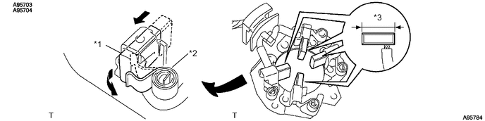
Text in Illustration *1 Brush *2 Spring *3 Length - - -
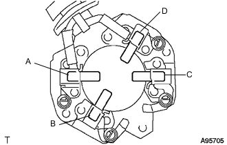
Check the brush holder.
-
Measure the resistance according to the value(s) in the table below.
Standard resistance Tester Connection Specified Condition A - B 10 kΩ or higher A - C 10 kΩ or higher A - D Below 1 Ω B - C Below 1 Ω B - D 10 kΩ or higher C - D 10 kΩ or higher If the standard is not met, replace the starter brush holder assembly.
-
-
-
INSPECT STARTER CENTER BEARING CLUTCH SUB-ASSEMBLY
-
Inspect the gear teeth on the planetary gear, internal gear and starter clutch for wear and damage.
If damaged, replace the gear or clutch assembly. Also check the planetary gear for wear and damage.
-
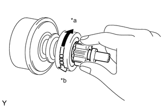
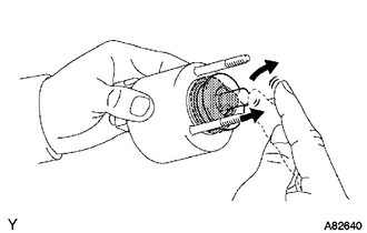
Text in Illustration *a Free *b Lock Inspect the starter clutch.
-
Rotate the clutch pinion gear clockwise and check that it turns freely. Try to rotate the clutch pinion gear counterclockwise and check that it locks.
If necessary, replace the starter center bearing clutch sub-assembly.
-
-