STARTER(w/ Stop And Start System) REASSEMBLY
PROCEDURE
-
INSTALL STARTER CLUTCH SUB-ASSEMBLY
-
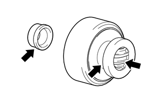
Apply high-temperature grease to the bushing and spline of the starter clutch sub-assembly and stop collar.
Text in Illustration 
High-temperature Grease -
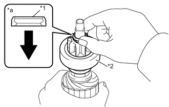
Text in Illustration *1 Stop Collar *2 Starter Clutch Sub-assembly *a Cross Section Drawing Starter Clutch Sub-assembly Side Place the starter clutch sub-assembly and stop collar to the starter armature assembly.
-
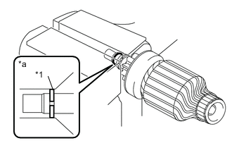
Text in Illustration *1 Snap Ring *a Cross Section Drawing Apply high-temperature grease to a new snap ring, and install it to the groove of the starter armature assembly.
-
Using a vise between aluminum plates, compress the snap ring.
Note
Do not overtighten the vise.
-
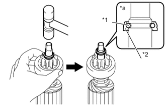
Text in Illustration *1 Snap Ring *2 Stop Collar *a Cross Section Drawing Using a plastic-faced hammer, while holding the starter clutch sub-assembly, tap the starter armature assembly and engage the stop collar to the snap ring.
Note
Do not tap the starter armature assembly too strongly.
-
-
INSTALL STARTER ARMATURE ASSEMBLY
-
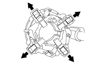
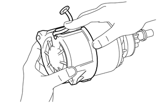
As shown in the illustration, push out the 4 brushes of the starter yoke assembly towards the outer side and them there.
Push Out -
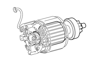
Install the starter armature assembly to the starter yoke assembly.
-
Secure the starter armature assembly shaft in a vise between aluminum plates.
Note
Do not overtighten the vise.
-
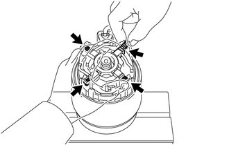
Install the 4 brush springs.
Note
Make sure the brush spring does not fly out.
-
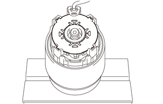
Install the brush holder insulator to the brush holder of the starter yoke assembly.
-
-
INSTALL STARTER COMMUTATOR END FRAME ASSEMBLY
-
Install the starter commutator end frame to the starter yoke assembly.
Note
While holding down the lead wire, install the starter commutator end frame assembly.
-
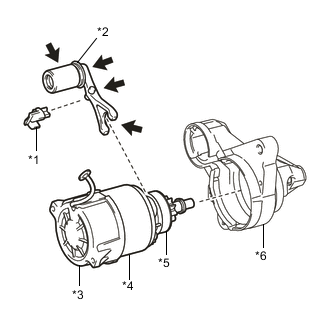
Text in Illustration *1 Rubber Seal *2 Starter Pinion Drive Lever *3 Starter Commutator End Frame Assembly. *4 Starter Yoke Assembly *5 Starter Clutch Sub-assembly *6 Starter Drive Housing Assembly High-temperature Grease Apply high-temperature grease to the parts of the starter pinion drive lever that contact the magnet starter switch assembly, starter clutch sub-assembly and starter drive housing assembly.
-
Install the starter pinion drive lever to the starter clutch sub-assembly.
-
Install the starter commutator end frame assembly together with starter yoke assembly, starter pinion drive lever and rubber seal to the starter drive housing assembly.
-
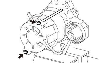
Install the 2 through bolts.
- Torque:
- 6.4 N*m { 65 kgf*cm, 57 in.*lbf }
-
-
INSTALL MAGNET STARTER SWITCH ASSEMBLY
-
Install the return spring to the starter pinion drive lever.
-
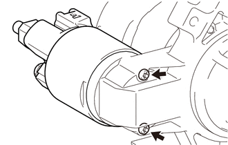
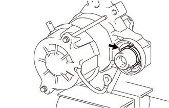
Using "TORX" socket wrench T20, install the magnet starter switch assembly to the starter drive housing assembly with the 2 bolts.
- Torque:
- 3.8 N*m { 39 kgf*cm, 34 in.*lbf }
-
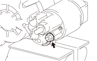
Install the wire harness to the terminal 45 with the nut.
- Torque:
- 8.0 N*m { 82 kgf*cm, 71 in.*lbf }
-