OIL PUMP INSTALLATION

CAUTION / NOTICE / HINT
PROCEDURE
-
INSTALL OIL PUMP ASSEMBLY
-
Install the oil pump assembly with the 3 bolts.
- Torque:
- 21 N*m { 214 kgf*cm, 15 ft.*lbf }
-
-
INSTALL NO. 2 OIL PAN SUB-ASSEMBLY
-
Remove any old packing material.
Note
Be careful not to drop any oil on the contact surfaces of the cylinder block sub-assembly and No. 2 oil pan sub-assembly.
-
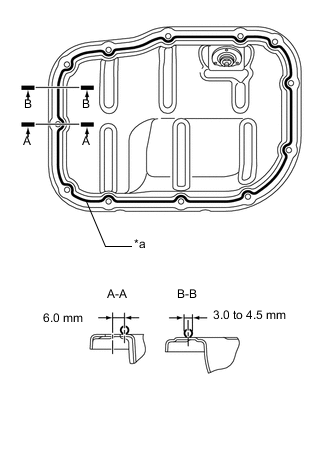
*a Seal Packing Apply seal packing as shown in the illustration.
Seal Packing Application Chart Seal Packing Diameter Application Position from Bolt Hole Center Seal Packing 3.0 to 4.5 mm
(0.118 to 0.177 in.)
6.0 mm (0.236 in.) Toyota Genuine Seal Packing Black, Three Bond 1207B or equivalent Note
-
Remove any oil from the contact surfaces.
-
Install the No. 2 oil pan sub-assembly within 3 minutes of applying seal packing.
-
Tighten the bolts and nuts within 15 minutes of applying seal packing.
-
Do not add engine oil for at least 2 hours after installation.
-
-
Install the No. 2 oil pan sub-assembly with the 10 bolts and 2 nuts.
- Torque:
- 10 N*m { 102 kgf*cm, 7 ft.*lbf }
-
-
INSTALL NO.2 CHAIN SUB-ASSEMBLY
-
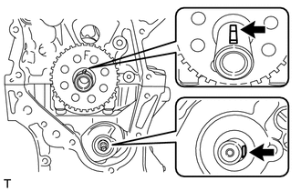
Set the crankshaft key as shown in the illustration.
-
Turn the drive shaft so that the cutout faces the right horizontal position.
-
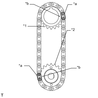
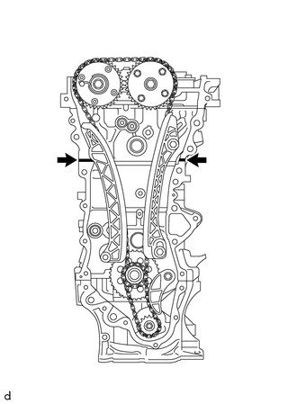
*1 Oil Pump Drive Gear *2 Oil Pump Driveshaft Gear *a Mark Plate *b Timing Mark Align the yellow mark plates with the timing marks of each gear as shown in the illustration.
-
Install the oil pump drive gear onto the crankshaft and install the oil pump driveshaft gear onto the oil pump shaft with the No. 2 chain sub-assembly on the gears.
-
Temporarily tighten the oil pump driveshaft gear with the nut.
-
Insert the damper spring into the hole of the chain tensioner plate, and then install the chain tensioner plate with the bolt.
- Torque:
- 10 N*m { 102 kgf*cm, 7 ft.*lbf }
-
Align the adjusting hole of the oil pump driveshaft gear with the groove of the oil pump assembly.
-
Insert a 3 mm diameter bar into the adjusting hole of the oil pump driveshaft gear to lock the gear in position, and then tighten the nut.
- Torque:
- 28 N*m { 286 kgf*cm, 21 ft.*lbf }
-
-
INSTALL CRANKSHAFT TIMING SPROCKET
-
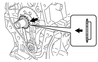

Engine Front Install the crankshaft timing sprocket as shown in the illustration.
-
-
INSTALL NO. 1 CHAIN VIBRATION DAMPER
-
INSTALL CHAIN SUB-ASSEMBLY
-
INSTALL CHAIN TENSIONER SLIPPER
-
INSTALL NO. 2 CHAIN VIBRATION DAMPER
-
Install the No. 2 chain vibration damper with the 2 bolts.
- Torque:
- 10 N*m { 102 kgf*cm, 7 ft.*lbf }
-
-
INSTALL TIMING CHAIN COVER SUB-ASSEMBLY
-
Remove any remaining seal packing material.
-
Clean the contact surfaces of the timing chain cover sub-assembly, camshaft housing sub-assembly, cylinder head sub-assembly, cylinder block sub-assembly and stiffening crankcase assembly, and confirm that no oil, moisture, or other foreign matter is on the surfaces.
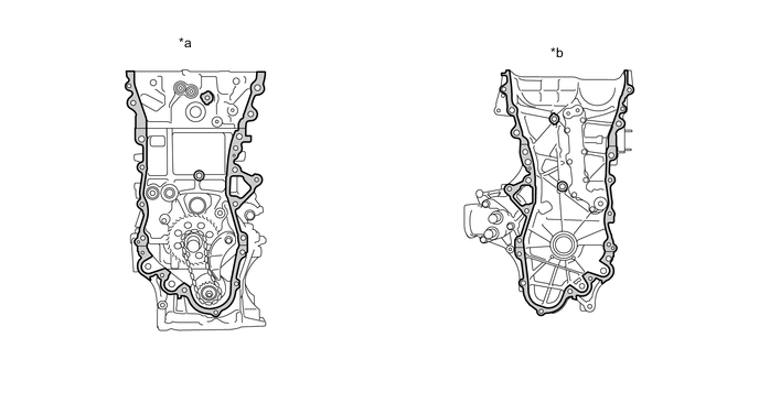
*a Engine Side *b Timing Chain Cover Side 
Clean and degrease - - -
Install 3 new O-rings.
-
Apply seal packing as shown in the illustration.
Seal Packing Toyota Genuine Seal Packing Black, Three Bond 1207B or equivalent Standard Seal Diameter 5.0 mm (0.197 in.) Note
-
If there is oil on the contact surfaces, wipe them with an oil-free cloth before applying seal packing.
-
Install the timing chain cover sub-assembly within 3 minutes and tighten the bolts within 10 minutes of applying seal packing.
-
Do not add engine oil for at least 2 hours.
-
-
Apply seal packing to the timing chain cover sub-assembly in a continuous line as shown in the illustration.
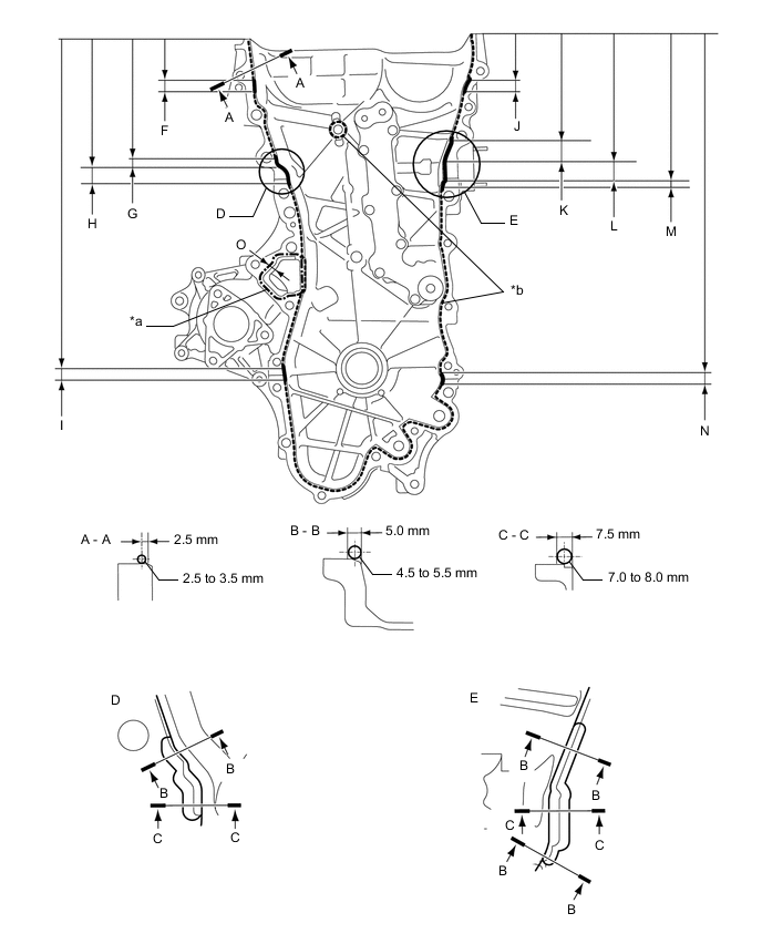
*a Toyota Genuine Seal Packing Black 1282B, Three Bond 1282B or equivalent *b Toyota Genuine Seal Packing Black, Three Bond 1207B or equivalent Seal Packing Item Seal Packing Dashed line Toyota Genuine Seal Packing Black, Three Bond 1207B or equivalent Continuous line Alternate long and short dashed line Toyota Genuine Seal Packing 1282B, Three Bond 1282B or equivalent Seal Packing Application Chart Area Seal Packing Diameter Distance from Edge of Cover to: Seal Packing Application Length Distance from Top of Cover to Top of Seal Packing Dashed Line Area 2.5 to 3.5 mm (0.0984 to 0.138 in.) Center of seal packing
2.5 mm (0.0984 in.)
- - Continuous Line Area 4.5 to 5.5 mm (0.177 to 0.217 in.) or 7.0 to 8.0 mm (0.276 to 0.315 in.) - - - Alternate long and short dashed line 4.0 mm (0.157 in.) Center of seal packing
3.0 mm (0.118 in.)
- - A - A 2.5 to 3.5 (0.0984 to 0.138) Center of seal packing
2.5 mm (0.0984 in.)
- - B - B 4.5 to 5.5 (0.177 to 0.217) Center of seal packing
5.0 mm (0.197 in.)
- - C - C 7.0 to 8.0 (0.276 to 0.315) Opposite edge of seal packing
7.5 mm (0.295 in.)
- - F 4.5 to 5.5 mm (0.177 to 0.217 in.) - 15.5 mm (0.610 in.) 50.4 mm (1.98 in.) G 4.5 to 5.5 mm (0.177 to 0.217 in.) - 10.3 mm (0.406 in.) 143.1 mm (5.63 in.) H 7.0 to 8.0 mm (0.276 to 0.315 in.) - 19.5 mm (0.768 in.) 153.4 mm (6.04 in.) I 4.5 to 5.5 mm (0.177 to 0.217 in.) - 16.0 mm (0.630 in.) 385.8 mm (1.27 ft.) J 4.5 to 5.5 mm (0.177 to 0.217 in.) - 18.6 mm (0.732 in.) 51.4 mm (2.02 in.) K 4.5 to 5.5 mm (0.177 to 0.217 in.) - 25.3 mm (0.996 in.) 121.9 mm (4.80 in.) L 7.0 to 8.0 mm (0.276 to 0.315 in.) - 25.8 mm (1.02 in.) 147.2 mm (5.80 in.) M 4.5 to 5.5 mm (0.177 to 0.217 in.) - 5.1 mm (0.201 in.) 173.0 mm (6.81 in.) N 4.5 to 5.5 mm (0.177 to 0.217 in.) - 14.6 mm (0.575 in.) 385.8 mm (1.27 ft.) O 4.0 mm (0.157 in.) Center of seal packing
3.0 mm (0.118 in.)
- - Note
-
If there is oil on the contact surfaces, wipe them with an oil-free cloth before applying seal packing.
-
Install the timing chain cover sub-assembly within 3 minutes and tighten the bolts within 10 minutes of applying seal packing.
-
After applying seal packing to the timing chain cover sub-assembly, install the engine mounting bracket RH and oil filter bracket within 10 minutes.
-
Do not add engine oil for at least 2 hours after installation.
-
-
Temporarily install the timing chain cover sub-assembly.
-
Install a new water pump gasket.
Note
Remove any oil from the contact surfaces.
-
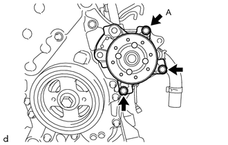
Install the water pump with the 3 bolts.
- Torque:
- 21 N*m { 214 kgf*cm, 15 ft.*lbf }
Tech Tips
As final tightening of bolt A will be performed when installing the supercharger, temporarily tighten it at this time.
-
Temporarily install the engine mounting bracket RH with the 3 bolts.
Note
-
Install the mounting bracket within 10 minutes of installing the timing chain cover sub-assembly.
-
Do not start the engine for at least 2 hours after installation.
Bolt Length Item Length Bolt 80 mm (3.15 in.) -
-
Install 2 new O-rings.
-
Temporarily install the oil filter bracket with the 4 bolts.
Note
-
Install the oil filter bracket within 10 minutes of installing the chain cover.
-
Do not start the engine for at least 2 hours after installation.
Bolt Length Item Length Bolt 35 mm (1.38 in.) -
-
Install the timing chain cover sub-assembly with the 26 bolts and a new seal washer in the order shown in the illustration.
Note
-
Install the timing chain cover sub-assembly within 3 minutes and tighten the bolts within 10 minutes of applying seal packing.
-
Do not add engine oil for at least 2 hours after installation.
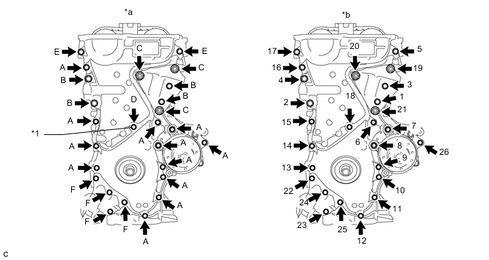
*1 Seal Washer - - *a Torque *b Bolt Torque Order - Torque:
- Bolt (A), (E)
- 25.5 N*m { 260 kgf*cm, 19 ft.*lbf }
- Bolt (B), (C)
- 51 N*m { 520 kgf*cm, 38 ft.*lbf }
- Bolt (D)
- 10 N*m { 102 kgf*cm, 7 ft.*lbf }
- Bolt (F)
- 25 N*m { 255 kgf*cm, 18 ft.*lbf }
Tech Tips
Apply adhesive to the threads of bolt (E).
Adhesive Toyota Genuine Adhesive 1324, Three Bond 1324 or equivalent Bolt Length Item Length Bolt (A), (E) 35 mm (1.38 in.) Bolt (B) 55 mm (2.17 in.) Bolt (C) 80 mm (3.15 in.) Bolt (D) 40 mm (1.57 in.) -
-
Using a 8 mm socket wrench, install the stud bolt to the engine mounting bracket RH.
- Torque:
- 10 N*m { 102 kgf*cm, 7 ft.*lbf }
-
Install a new gasket to the oil cooler hose.
-
Install the oil cooler hose to the oil filter bracket assembly with the bolt.
- Torque:
- 72.5 N*m { 739 kgf*cm, 53 ft.*lbf }
-
Install a new gasket to the No. 1 oil cooler hose.
-
Install the No. 1 oil cooler hose to the oil filter bracket assembly with the bolt.
- Torque:
- 72.5 N*m { 739 kgf*cm, 53 ft.*lbf }
-
-
INSTALL TIMING CHAIN OR BELT COVER OIL SEAL
-
INSTALL CRANKSHAFT PULLEY
-
INSTALL NO. 1 CHAIN TENSIONER ASSEMBLY
-
INSTALL CYLINDER HEAD COVER GASKET
-
INSTALL CYLINDER HEAD COVER SUB-ASSEMBLY
-
INSTALL THERMOSTAT
-
INSTALL WATER INLET
-
INSTALL WATER INLET HOSE
-
INSTALL WATER BY-PASS HOSE
-
INSTALL NO. 1 WATER BY-PASS PIPE
-
CONNECT NO. 3 WATER BY-PASS HOSE
-
INSTALL VENTILATION HOSE
-
REMOVE CRANKSHAFT POSITION SENSOR HEAT SHIELD
-
INSTALL SUPERCHARGER NOSE SUPPORT BRACKET
-
INSPECT EXHAUST MANIFOLD
-
INSTALL EXHAUST MANIFOLD
-
REMOVE ENGINE TO ENGINE STAND
-
INSTALL IGNITION COIL ASSEMBLY
-
INSTALL FUEL INJECTOR ASSEMBLY
-
INSTALL NO. 1 DELIVERY PIPE SPACER
-
INSTALL FUEL DELIVERY PIPE
-
INSTALL AIR TUBE
-
INSTALL INTERCOOLER RESERVOIR TANK BRACKET
-
INSTALL SUPERCHARGER ASSEMBLY
-
INSTALL NO. 2 WATER BY-PASS HOSE
-
INSTALL NO. 1 WATER BY-PASS HOSE
-
INSTALL ENGINE OIL LEVEL DIPSTICK GUIDE
-
INSTALL ENGINE OIL LEVEL DIPSTICK SUB-ASSEMBLY
-
INSTALL ENGINE HANGER