OIL PUMP INSTALLATION

PROCEDURE
-
INSTALL STUD BOLT
-
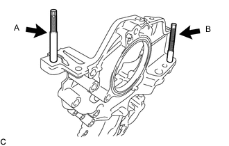
Using an E8 "TORX" socket wrench, install the stud bolt A to the timing chain cover assembly.
- Torque:
- 7.5 N*m { 76 kgf*cm, 66 in.*lbf }
-
Install the stud bolt B to the timing chain cover assembly.
- Torque:
- 10 N*m { 102 kgf*cm, 7 ft.*lbf }
-
-
INSTALL TIMING CHAIN COVER OIL SEAL
-
Apply a light coat of MP grease to a new timing chain cover oil seal lip.
Note
Keep the timing chain cover oil seal lip free of foreign matter.
-
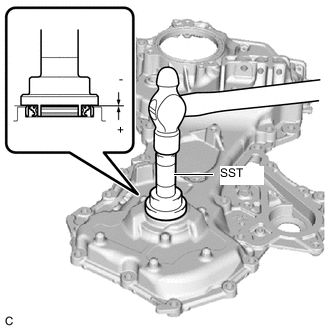
Using SST and a hammer, tap in the timing chain cover oil seal until its surface is flush with the timing chain cover assembly edge.
- SST
- 09223-22010
Standard Depth -0.5 to 1.0 mm (-0.0197 to 0.0394 in.) (From the edge of the timing chain cover assembly) Note
Do not tap in the timing chain cover oil seal at an angle.
-
-
INSTALL TIMING CHAIN COVER ASSEMBLY
-
Clean and degrease the threads of the No. 1 timing gear cover tight plug.
-
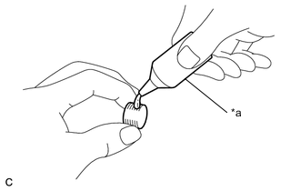
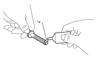
*a Adhesive Apply adhesive to 2 or 3 threads of the No. 1 timing gear cover tight plug.
Adhesive Toyota Genuine Adhesive 1324, Three Bond 1324 or equivalent Note
To prevent contamination by foreign matter, install immediately after applying adhesive.
-
Using an 8 mm socket hexagon wrench, install the No. 1 timing gear cover tight plug to the timing chain cover assembly.
- Torque:
- 15 N*m { 153 kgf*cm, 11 ft.*lbf }
Note
Do not start the engine for at least 1 hour after installation.
-
Remove any old seal packing remaining on the sealing surfaces.
-
Clean the contact surfaces of the timing chain cover assembly, camshaft housing sub-assembly, cylinder head sub-assembly, cylinder block sub-assembly and oil pan sub-assembly and confirm that no oil, moisture or other foreign matters are on the surfaces.
-
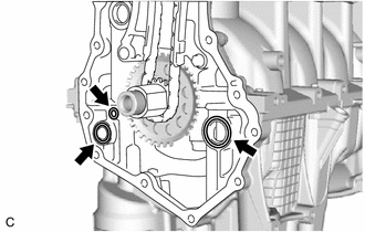
Install 3 new O-rings to the oil pan sub-assembly.
-
Apply seal packing to the timing chain cover assembly as shown in the illustration.
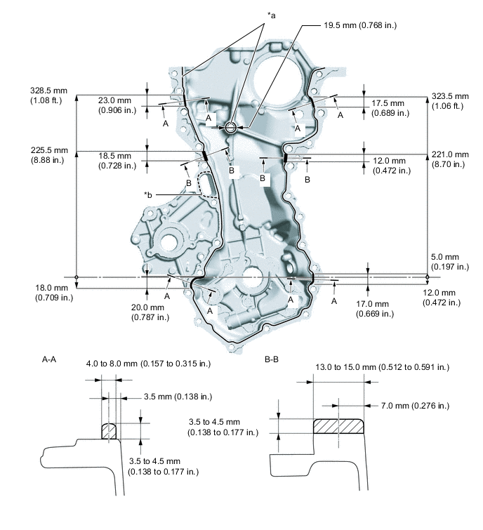
*a Toyota Genuine Seal Packing Black, Three Bond 1207B or equivalent *b Toyota Genuine Seal Packing 1282B, Three Bond 1282B or equivalent Note
-
If the contact surfaces are wet, wipe them with an oil-free cloth before applying seal packing.
-
Install the timing chain cover assembly within 3 minutes and tighten the bolts within 10 minutes of applying seal packing.
-
Do not add engine oil for at least 2 hours after installation.
-
Do not start the engine for at least 2 hours after installation.
Tech Tips
Areas A-A and B-B are the joints between the cylinder block sub-assembly and oil pan sub-assembly, cylinder block sub-assembly and cylinder head sub-assembly, and cylinder head sub-assembly and camshaft housing sub-assembly.
Application Specification Area Seal Packing Diameter Seal Packing Continuous Line Area
Continuous Line Area (except A-A, B-B)
3.5 to 4.5 mm (0.138 to 0.177 in.) Toyota Genuine Seal Packing Black, Three Bond 1207B or equivalent Dashed Line Area 2.0 to 3.0 mm (0.0787 to 0.118 in.) Toyota Genuine Seal Packing 1282B, Three Bond 1282B or equivalent -
-
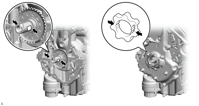
Align the oil pump drive rotor spline with crankshaft as shown in the illustration and install the timing chain cover assembly.
-
Clean and degrease the threads of the bolt B, bolt H and bolt E.
-
*a Adhesive Apply adhesive to the threads of the bolt E.
Adhesive Toyota Genuine Adhesive 1324, Three Bond 1324 or equivalent Note
To prevent contamination by foreign matter, install immediately after applying adhesive.
Tech Tips
Apply adhesive in the range of 7 mm or more from the tip of the bolt E.
-
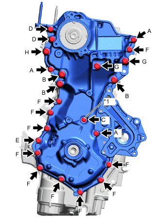
*1 Seal Washer Temporarily install the timing chain cover assembly with the 23 bolts and a new seal washer.
Note
Do not apply oil to the bolt B and bolt H.
Bolt Length Item Length Bolt A 40 mm (1.57 in.) Bolt B, H 50 mm (1.97 in.) Bolt C 35 mm (1.38 in.) Bolt D 70 mm (2.76 in.) Bolt E, F 25 mm (0.984 in.) Bolt G 80 mm (3.15 in.) -
Install a new water pump gasket to the engine water pump assembly.
-
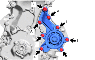
Temporarily install the engine water pump assembly to the timing chain cover assembly with the 8 bolts.
Note
Do not apply oil to the bolt B.
Bolt Length Item Length Bolt A 40 mm (1.57 in.) Bolt B 50 mm (1.97 in.) Bolt I 20 mm (0.787 in.) -
Fully tighten the 4 bolts I.
- Torque:
- 21 N*m { 214 kgf*cm, 15 ft.*lbf }
-
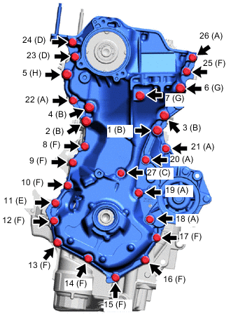
Fully tighten the 27 bolts in the order shown in the illustration.
- Torque:
- Bolt A, D, E, F
- 24 N*m { 245 kgf*cm, 18 ft.*lbf }
- Bolt B
- 60.3 N*m { 615 kgf*cm, 44 ft.*lbf }
- Bolt C
- 10 N*m { 102 kgf*cm, 7 ft.*lbf }
- Bolt G, H
- 64 N*m { 653 kgf*cm, 47 ft.*lbf }
-
Wipe off any excess seal packing with a clean piece of cloth from the cylinder head cover sub-assembly contact surfaces.
-
-
INSTALL CRANKSHAFT PULLEY
-
INSTALL NO. 2 WATER INLET HOUSING GASKET
-
INSTALL WATER INLET WITH THERMOSTAT SUB-ASSEMBLY
-
INSTALL CRANKSHAFT POSITION SENSOR
-
INSTALL CAMSHAFT BEARING CAP OIL HOLE GASKET
-
INSTALL CYLINDER HEAD COVER GASKET
-
INSTALL CYLINDER HEAD COVER SUB-ASSEMBLY
-
INSTALL CAMSHAFT TIMING CONTROL MOTOR O-RING
-
INSTALL CAMSHAFT TIMING CONTROL MOTOR WITH EDU ASSEMBLY
-
INSTALL NO. 1 IGNITION COIL
-
INSTALL V-RIBBED BELT TENSIONER ASSEMBLY
-
INSTALL NO. 2 WATER BY-PASS PIPE
-
INSTALL ENGINE WIRE
-
INSTALL NO. 1 INTAKE MANIFOLD TO HEAD GASKET
-
INSTALL INTAKE MANIFOLD
-
INSTALL PURGE VALVE (PURGE VSV)
-
INSTALL EGR PIPE GASKET
-
INSTALL EGR INLET GASKET
-
INSTALL EGR VALVE ASSEMBLY
-
CONNECT EGR PIPE ASSEMBLY
-
Connect the EGR pipe assembly to the exhaust manifold converter sub-assembly with the 2 nuts.
- Torque:
- 26 N*m { 265 kgf*cm, 19 ft.*lbf }
-
-
INSTALL VENTILATION HOSE ASSEMBLY
-
INSTALL ENGINE HANGER
-
REMOVE ENGINE STAND