OIL PUMP REMOVAL

PROCEDURE
-
INSTALL ENGINE TO ENGINE STAND
-
REMOVE ENGINE HANGER
-
REMOVE ENGINE OIL LEVEL DIPSTICK SUB-ASSEMBLY
-
REMOVE ENGINE OIL LEVEL DIPSTICK GUIDE
-
SEPARATE NO. 1 WATER BY-PASS HOSE
-
SEPARATE NO. 2 WATER BY-PASS HOSE
-
REMOVE SUPERCHARGER ASSEMBLY
-
REMOVE INTERCOOLER RESERVOIR TANK BRACKET
-
REMOVE AIR TUBE
-
REMOVE FUEL DELIVERY PIPE
-
REMOVE NO. 1 DELIVERY PIPE SPACER
-
REMOVE INJECTOR VIBRATION INSULATOR
-
REMOVE FUEL INJECTOR ASSEMBLY
-
REMOVE IGNITION COIL ASSEMBLY
-
REMOVE MANIFOLD STAY
-
REMOVE EXHAUST MANIFOLD
-
REMOVE SUPERCHARGER NOSE SUPPORT BRACKET
-
REMOVE CRANKSHAFT POSITION SENSOR HEAT SHIELD
-
REMOVE VENTILATION HOSE
-
SEPARATE NO. 3 WATER BY-PASS HOSE
-
REMOVE NO. 1 WATER BY-PASS PIPE
-
REMOVE WATER BY-PASS HOSE
-
REMOVE WATER INLET HOSE
-
REMOVE WATER INLET
-
REMOVE THERMOSTAT
-
REMOVE ALTERNATOR TENSIONER BRACKET
-
REMOVE CYLINDER HEAD COVER SUB-ASSEMBLY
-
REMOVE CYLINDER HEAD COVER GASKET
-
SET NO. 1 CYLINDER TO TDC/COMPRESSION
-
REMOVE CRANKSHAFT PULLEY
-
REMOVE NO. 1 CHAIN TENSIONER ASSEMBLY
-
REMOVE TIMING CHAIN COVER SUB-ASSEMBLY
-
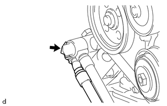
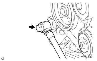
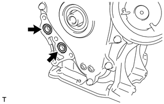
Using an 8 mm socket wrench, remove the stud bolt from the engine mounting bracket RH.
-
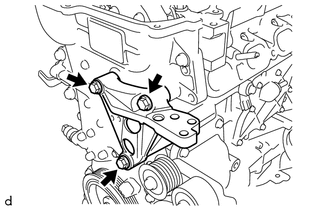
Remove the 3 bolts and engine mounting bracket RH.
-
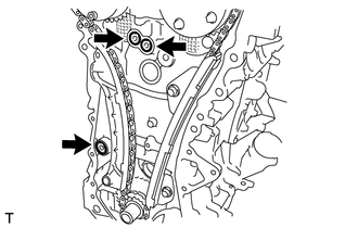
Remove the bolt and No. 1 oil cooler hose from the oil filter bracket assembly.
-
Remove the gasket.
-
Remove the bolt and oil cooler hose from the oil filter bracket assembly.
-
Remove the gasket.
-
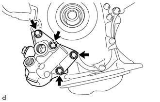
Remove the 4 bolts and oil filter bracket.
-
Remove the 2 O-rings.
-
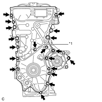
*1 Seal Washer Remove the 19 bolts and seal washer.
-
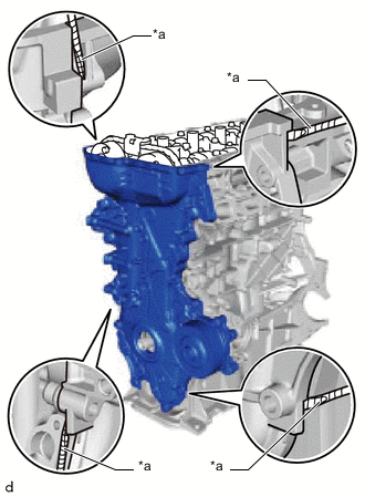
*a Protective Tape Remove the timing chain cover sub-assembly by prying between the timing chain cover sub-assembly and cylinder head sub-assembly or cylinder block sub-assembly with a screwdriver.
Note
Be careful not to damage the contact surfaces of the timing chain cover sub-assembly, cylinder block sub-assembly, and cylinder head sub-assembly.
Tech Tips
Tape the screwdriver tip before use.
-
Remove the 3 O-rings.
-

Remove the 3 bolts and water pump.
-
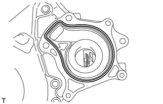
Remove the water pump gasket.
-
-
REMOVE TIMING CHAIN COVER OIL SEAL
-
REMOVE NO. 2 CHAIN VIBRATION DAMPER
-
REMOVE CHAIN TENSIONER SLIPPER
-
REMOVE NO. 1 CHAIN VIBRATION DAMPER
-
REMOVE CHAIN SUB-ASSEMBLY
-
REMOVE CRANKSHAFT TIMING SPROCKET
-
Remove the crankshaft timing sprocket.
-
-
REMOVE NO. 2 CHAIN SUB-ASSEMBLY
-
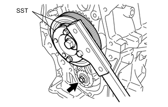
Temporarily install the crankshaft pulley and crankshaft pulley set bolt.
-
Using SST, hold the crankshaft pulley. Then remove the oil pump drive shaft gear nut.
- SST
- 09213-54015
Tech Tips
Part number of the installation bolt for SST (crankshaft pulley holding tool): 91551-00850 (quantity: 2)
-
Remove SST, the crankshaft pulley set bolt and crankshaft pulley.
-
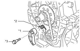
*1 Chain Tensioner Plate *2 Chain Damper Spring *3 Bolt Remove the bolt, chain tensioner plate and chain damper spring.
-
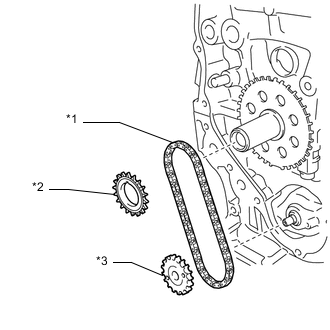
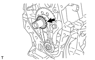
*1 No. 2 Chain Sub-assembly *2 Oil Pump Drive Gear *3 Oil Pump Drive Shaft Gear Remove the oil pump drive gear, oil pump driveshaft gear, and No. 2 chain sub-assembly.
-
-
REMOVE NO. 2 OIL PAN SUB-ASSEMBLY
-
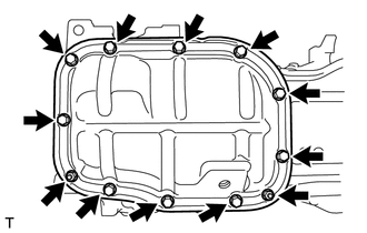
Remove the 10 bolts and 2 nuts.
-
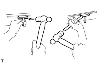
Insert the blade of oil pan seal cutter between the crankcase and No. 2 oil pan sub-assembly. Cut through the applied sealer and remove the No. 2 oil pan sub-assembly.
Note
Be careful not to damage the contact surfaces of the crankcase and No. 2 oil pan sub-assembly.
-
-
REMOVE OIL PUMP ASSEMBLY
-
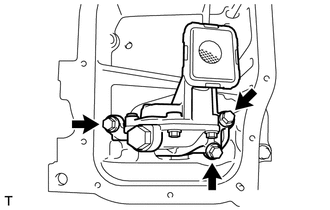
Remove the 3 bolts and oil pump assembly.
-