OIL PUMP INSTALLATION

PROCEDURE
-
INSTALL TIMING CHAIN COVER OIL SEAL
-
INSTALL STUD BOLT (for TMC Made)
-
INSTALL STUD BOLT (for TMMF Made)
-
INSTALL TIMING CHAIN COVER SUB-ASSEMBLY
-
Remove any old packing material remaining on the sealing surfaces before applying seal packing.
-
Clean and degrease the contact surfaces of the timing chain cover, cylinder head, cylinder block and confirm that no oil, moisture, or other foreign matter remains on the surfaces.
-
Install a new oil pump gasket to the cylinder block.
-
Apply seal packing to the timing chain cover as shown in the following illustration.
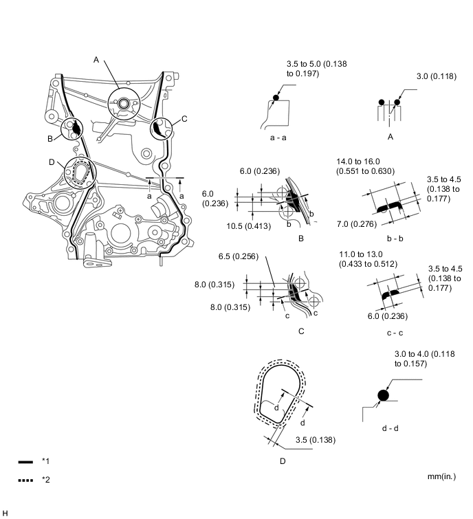
Text in Illustration *1 Toyota Genuine Seal Packing Black, Three Bond 1207B *2 Toyota Genuine Seal Packing 1282B, Three Bond 1282B Seal packing Water pump: Toyota Genuine Seal Packing 1282B, Three Bond 1282B or equivalent Other: Toyota Genuine Seal Packing Black, Three Bond 1207B or equivalent Note
-
When there is oil on the contact surfaces, wipe them with an oil-free cloth before applying seal packing.
-
Install the chain cover within 3 minutes and tighten the bolts within 10 minutes after applying seal packing.
-
Do not start the engine for at least 2 hours after installing.
-
-
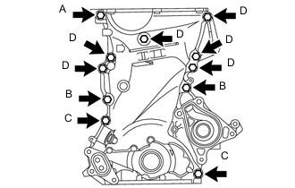
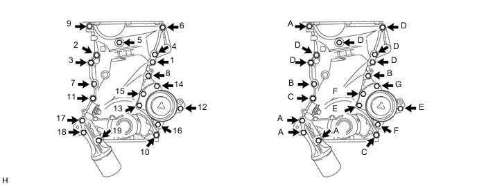
Temporarily install the timing chain cover with the 11 bolts.
Bolt Length Item Length Bolt A 80 mm (3.150 in.) Bolt B 40 mm (1.575 in.) Bolt C
(with washer)
45 mm (1.772 in.) Bolt D 70 mm (2.756 in.) -
Install a new oil filter bracket gasket to the timing chain cover.
-
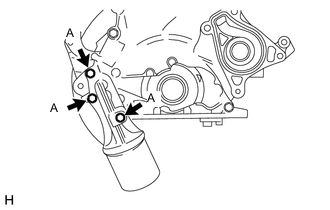
Temporarily install the oil filter bracket with the 3 bolts.
Bolt Length Item Length Bolt A 80 mm (3.150 in.) -
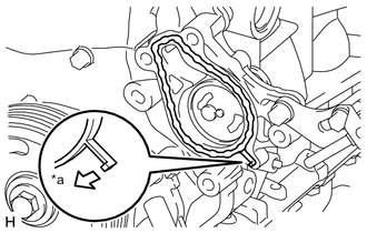
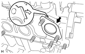
Text in Illustration *a Water Pump Side Install a new water pump gasket to the timing chain cover.
-
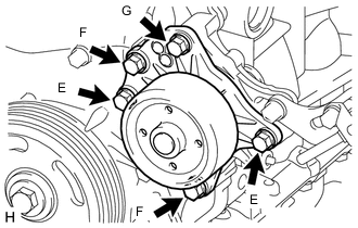
Temporarily install the water pump with the 5 bolts.
Bolt Length Item Length Bolt E 20 mm (0.787 in.) Bolt F 50 mm (1.969 in.) Bolt G 45 mm (1.772 in.) -
Fully tighten the timing chain cover with the 19 bolts in the order shown in the illustration.
- Torque:
- Bolt A, C
- 24 N*m { 245 kgf*cm, 18 ft.*lbf }
- Bolt B, D
- 40 N*m { 408 kgf*cm, 30 ft.*lbf }
- Bolt E, F, G
- 28 N*m { 286 kgf*cm, 21 ft.*lbf }
Bolt Length Item Length Bolt A 80 mm (3.150 in.) Bolt B 40 mm (1.575 in.) Bolt C
(with washer)
45 mm (1.772 in.) Bolt D 70 mm (2.756 in.) Bolt E 20 mm (0.787 in.) Bolt F 50 mm (1.969 in.) Bolt G 45 mm (1.772 in.) -
Wipe off the excess seal packing.
-
-
INSTALL DRAIN PLUG
-
INSTALL TIGHT PLUG
-
INSTALL CRANKSHAFT PULLEY
-
INSTALL OIL STRAINER SUB-ASSEMBLY
-
INSTALL OIL PAN SUB-ASSEMBLY (for TMC Made)
-
INSTALL OIL PAN SUB-ASSEMBLY (for TMMF Made)
-
INSTALL NO. 1 WATER BY-PASS PIPE
-
Text in Illustration *a Water By-pass Pipe Side Install a new water by-pass pipe gasket to the cylinder head.
-
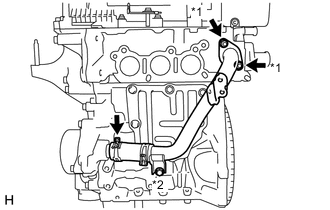
Text in Illustration *1 Nut *2 Bolt Insert the water by-pass hose to the timing chain cover.
-
Temporarily install the water by-pass pipe with the bolt and 2 nuts.
-
Fully tighten the 2 nuts.
- Torque:
- 24 N*m { 245 kgf*cm, 18 ft.*lbf }
-
Fully tighten the bolt.
- Torque:
- 24 N*m { 245 kgf*cm, 18 ft.*lbf }
-
-
INSTALL CYLINDER HEAD COVER SUB-ASSEMBLY
-
CONNECT VENTILATION HOSE
-
INSTALL DUTY VACUUM SWITCHING VALVE
-
INSTALL NO. 1 IGNITION COIL
-
INSTALL CRANKSHAFT POSITION SENSOR
-
INSTALL CAMSHAFT TIMING OIL CONTROL VALVE ASSEMBLY
-
INSTALL EXHAUST MANIFOLD CONVERTER SUB-ASSEMBLY
-
INSTALL MANIFOLD STAY
-
INSTALL EGR INLET EXHAUST MANIFOLD PLATE
-
INSTALL ENGINE OIL LEVEL DIPSTICK GUIDE
-
INSTALL ENGINE OIL LEVEL DIPSTICK SUB-ASSEMBLY
-
INSTALL AIR CLEANER FILTER ELEMENT SUB-ASSEMBLY
-
INSTALL AIR CLEANER CAP SUB-ASSEMBLY
-
INSTALL ENGINE ASSEMBLY