STEERING GEAR INSPECTION

PROCEDURE
-
INSPECT TIE ROD END SUB-ASSEMBLY LH
-
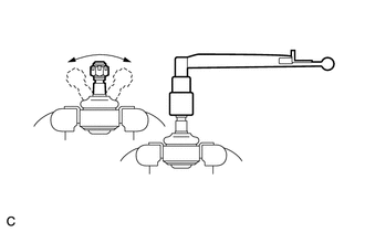
Secure the tie rod end sub-assembly LH in a vise.
Note
Do not overtighten the vise.
-
Install the nut onto the stud bolt.
-
Flip the ball joint back and forth 5 times.
-
Set a torque wrench to the nut, turn the ball joint continuously at a rate of 2 to 4 seconds per turn, and check the turning torque on the 5th turn.
Standard turning torque 0.29 to 1.96 N*m (2.96 to 20.0 kgf*cm, 2.57 to 17.3 in.*lbf) Tech Tips
If turning torque is not within the specified range, replace the tie rod end sub-assembly LH with a new one.
-
-
INSPECT TIE ROD END SUB-ASSEMBLY RH
Tech Tips
Perform the same procedure as for the LH side.
-
INSPECT TOTAL PRELOAD
-
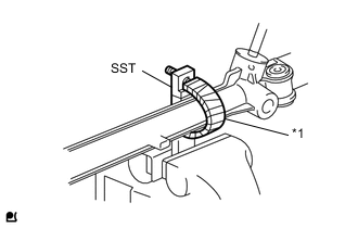
Text in Illustration *1 Protective Tape Using SST, secure the steering gear in a vise.
- SST
- 09612-00012
Tech Tips
Tape SST before use.
-
Using SST, fully turn the steering rack right and left 1 to 2 times to settle it.
- SST
- 09616-00011
-
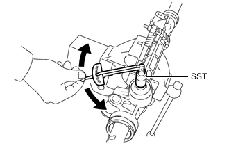
Using SST and a torque wrench, turn the pinion at a fixed speed between 4 to 6 seconds and check the total turning torque.
- SST
- 09616-00011
Standard preload Type Tire Size preload TMC Made 175/70R14
175/65R15
0.57 to 1.17 N*m (5.9 to 11.9 kgf*cm, 5.1 to 10.3 in.*lbf) 175/65R14
185/60R15
0.6 to 1.2 N*m (6.1 to 12.2 kgf*cm, 5.3 to 10.6 in.*lbf) TMMF Made ALL 0.57 to 1.17 N*m (5.9 to 11.9 kgf*cm, 5.1 to 10.3 in.*lbf) Note
Remove the steering rack boot before measurement.
Tech Tips
-
Inspect around the steering rack center position.
-
If the total preload is not within the specified range, replace the steering gear assembly with a new one.
-