STEERING COLUMN ASSEMBLY(for LHD) REASSEMBLY

PROCEDURE
-
INSTALL POWER STEERING MOTOR ASSEMBLY (for TMC Made)
Note
-
Do not drop the power steering motor assembly, strike it with tools or subject it to impacts.
-
If the power steering motor assembly is subjected to an impact, replace it with a new one.
-
Do not pull the wire harness and tilt steering support bond cable of the power steering motor assembly.
-
Do not allow any moisture to come into contact with the power steering motor assembly.
-
Do not loosen any bolts not mentioned in the procedure.
-
Do not allow any foreign objects to contaminate the power steering motor assembly.
-
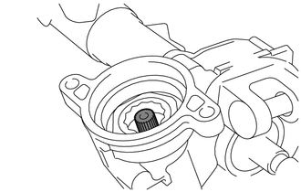
Apply grease to the serrated part of the electric power steering column sub-assembly.
Note
First wipe off the existing grease from the serrated part, and then apply the dedicated grease supplied with a new power steering motor assembly or electric power steering column sub-assembly.
-
Temporarily install the power steering motor assembly to the electric power steering column subassembly with the 2 bolts.
Note
When temporarily installing the 2 bolts to the power steering motor assembly, do not tighten them all the way down.
-
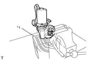
Text in Illustration *1 Wooden Block Secure the steering column assembly in a vise using aluminum plates.
Note
-
Do not overtighten the vise, as the steering column assembly may become deformed.
-
Secure the power steering motor assembly so that it is directly upright.
-
Support the steering column assembly with a wooden block or similar item to ensure that it does not fall.
-
-
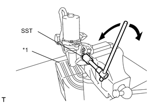
Text in Illustration *1 Wooden Block Using SST, turn the steering main shaft once 180 degrees to the left and then 180 degrees to the right at a speed of 60 rpm, and repeat 2 to 3 times to adjust the axis centering of the power steering motor assembly.
- SST
- 09616-00011
-
Tighten the 2 bolts.
- Torque:
- 19 N*m { 189 kgf*cm, 14 ft.*lbf }
-
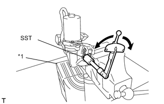
Text in Illustration *1 Wooden Block Using SST, measure the turning torque of the steering main shaft.
- SST
- 09616-00011
- Torque:
- Turning torque
- 1.45 N*m { 14.8 kgf*cm, 12.8 in.*lbf }
- or less
Note
Ensure that there is no abnormal resistance during rotation.
If the torque is not as specified, readjust the axis centering of the power steering motor assembly.
-
Install new clamp and tape to the wire harness as shown in the illustration.
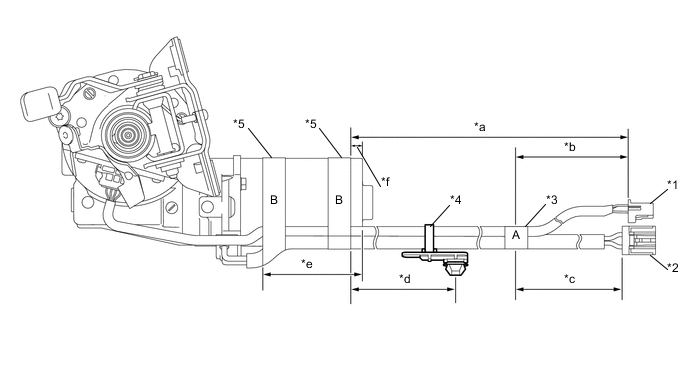
Text in Illustration *1 Torque Sensor Wire Harness *2 Power Steering Motor Wire Harness *3 Tape A *4 Clamp *5 Tape B - - *a 383 to 403 mm *b 100 mm *c 80 to 100 mm *d 155 to 175 mm *e 74 to 94 mm - - Note
-
Wrap the tape around the area marked as "A" in the illustration more than 1.5 times.
-
Wrap the tape around the area marked as "B" in the illustration more than 2 times.
-
As heat from the power steering motor assembly may generate smoke, use heat resistant tape (resistant to 100°C (212°F) or more).
-
-
-
INSTALL POWER STEERING MOTOR ASSEMBLY (for TMMF Made)
Note
-
Do not drop the power steering motor assembly, strike it with tools or subject it to impacts.
-
If the power steering motor assembly is subjected to an impact, replace it with a new one.
-
Do not pull the wire harness and tilt steering support bond cable of the power steering motor assembly.
-
Do not allow any moisture to come into contact with the power steering motor assembly.
-
Do not loosen any bolts not mentioned in the procedure.
-
Do not allow any foreign objects to contaminate the power steering motor assembly.
-
Apply grease to the serrated part of the electric power steering column sub-assembly.
Note
First wipe off the existing grease from the serrated part, and then apply the dedicated grease supplied with a new power steering motor assembly or electric power steering column sub-assembly.
-
Using "TORX" socket wrench T40, temporarily install the power steering motor assembly to the electric power steering column subassembly with the 2 bolts.
Note
When temporarily installing the 2 bolts to the power steering motor assembly, do not tighten them all the way down.
-
Text in Illustration *1 Wooden Block Secure the steering column assembly in a vise using aluminum plates.
Note
-
Do not overtighten the vise, as the steering column assembly may become deformed.
-
Secure the power steering motor assembly so that it is directly upright.
-
Support the steering column assembly with a wooden block or similar item to ensure that it does not fall.
-
-
Text in Illustration *1 Wooden Block Using SST, turn the steering main shaft once 180 degrees to the left and then 180 degrees to the right at a speed of 60 rpm, and repeat 2 to 3 times to adjust the axis centering of the power steering motor assembly.
- SST
- 09616-00011
-
Using "TORX" socket wrench T40, tighten the 2 bolts.
- Torque:
- 19 N*m { 189 kgf*cm, 14 ft.*lbf }
-
Text in Illustration *1 Wooden Block Using SST, measure the turning torque of the steering main shaft.
- SST
- 09616-00011
- Torque:
- Turning torque
- 1.45 N*m { 14.8 kgf*cm, 12.8 in.*lbf }
- or less
Note
Ensure that there is no abnormal resistance during rotation.
If the torque is not as specified, readjust the axis centering of the power steering motor assembly.
-
Install new clamp and tape to the wire harness as shown in the illustration.
Text in Illustration *1 Torque Sensor Wire Harness *2 Power Steering Motor Wire Harness *3 Tape A *4 Clamp *5 Tape B - - *a 378 to 398 mm *b 145 mm *c 130 to 170 mm *d 150 to 170 mm *e 74 to 94 mm - - Note
-
Wrap the tape around the area marked as "A" in the illustration more than 1.5 times.
-
Wrap the tape around the area marked as "B" in the illustration more than 2 times.
-
As heat from the power steering motor assembly may generate smoke, use heat resistant tape (resistant to 100°C (212°F) or more).
-
-
-
INSTALL IGNITION OR STARTER SWITCH ASSEMBLY (w/o Entry and Start System)
-
Engage the 2 claws to install the ignition or starter switch assembly onto the upper steering column bracket assembly.
-
-
INSTALL KEY INTER LOCK SOLENOID (for TMC Made without Entry and Start System)
-
Install the key inter lock solenoid onto the upper steering column bracket assembly with the screw.
-
-
INSTALL KEY INTER LOCK SOLENOID (for TMMF Made without Entry and Start System)
-
Install the key inter lock solenoid onto the upper steering column bracket assembly with the 2 screws.
-
-
INSTALL UN-LOCK WARNING SWITCH ASSEMBLY (w/o Entry and Start System)
-
Engage the 2 claws to install the un-lock warning switch assembly onto the upper steering column bracket assembly.
Tech Tips
Slide the un-lock warning switch assembly, in the direction shown by the arrow in the illustration, to install it.
-
-
INSTALL IGNITION SWITCH LOCK CYLINDER ASSEMBLY (w/o Entry and Start System)
-
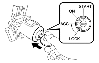
Turn the ignition switch to ACC.
-
Install the ignition switch lock cylinder assembly into the upper steering column bracket assembly.
-
Make sure that the ignition switch lock cylinder assembly is securely fixed onto the ignition switch lock cylinder assembly.
-
-
INSTALL UPPER STEERING COLUMN BRACKET ASSEMBLY (w/o Entry and Start System)
-
Set the steering column assembly in a vise between aluminum plates.
Note
Do not overtighten the vise.
-
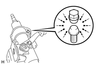
Install the steering column upper with switch bracket assembly with a new steering lock set bolt, and then tighten the bolt until its head comes off.
-
-
INSTALL STEERING LOCK ACTUATOR ASSEMBLY (w/ Entry and Start System)
-
Set the steering column assembly in a vise between aluminum plates.
Note
Do not overtighten the vise.
-
Install the steering lock actuator assembly with a new steering lock set bolt, and then tighten the bolt until its head comes off.
-
-
INSTALL TILT STEERING SUPPORT BOND CABLE
-
Install the tilt steering support bond cable with the 2 screws.
- Torque:
- 2.0 N*m { 20 kgf*cm, 18 in.*lbf }
-
-
INSTALL NO. 2 STEERING INTERMEDIATE SHAFT ASSEMBLY
-
Align the matchmarks on No. 2 steering intermediate shaft assembly and the steering column assembly and provisionally install them with the bolt.
Tech Tips
When either the steering column assembly or the No. 2 steering intermediate shaft assembly is replaced with a new one, they have no matchmarks, so align the marking (pink) on the steering column assembly shaft with the slit of the No. 2 steering intermediate shaft assembly, and install them.
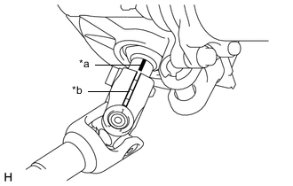
Text in Illustration *a Marking (Pink) *b Slit
-
-
INSTALL STEERING SLIDING YOKE SUB-ASSEMBLY
-
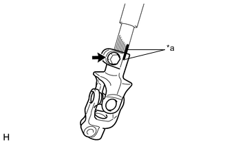
Text in Illustration *a Matchmark Align the matchmarks on No. 2 steering intermediate shaft assembly and the steering sliding yoke and provisionally install them with the bolt.
-