STEERING COLUMN ASSEMBLY(for LHD) REMOVAL

CAUTION / NOTICE / HINT
CAUTION:
Some of these service operations affect the SRS airbag system. Read the precautionary notices concerning the SRS airbag system before servicing Click here.
PROCEDURE
-
PRECAUTION
Note
After turning the ignition switch off, waiting time may be required before disconnecting the cable from the battery terminal. Therefore, make sure to read the disconnecting the cable from the battery terminal notice before proceeding with work Click here.
-
POSITION FRONT WHEELS FACING STRAIGHT AHEAD
-
DISCONNECT CABLE FROM NEGATIVE BATTERY TERMINAL
CAUTION:
Wait at least 90 seconds after disconnecting the cable from the negative (-) battery terminal to disable the SRS system.
-
REMOVE STEERING PAD (for TMC Made)
-
REMOVE STEERING PAD (for TMMF Made)
-
REMOVE STEERING WHEEL ASSEMBLY
-
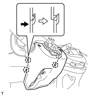
REMOVE STEERING COLUMN COVER SUPPORT (w/ Entry and Start System)
-
Disengage the 4 claws and remove the steering column cover support.
-
-
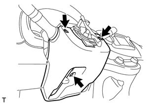
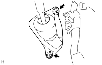
REMOVE LOWER STEERING COLUMN COVER
-
Remove the 3 screws.
-
Disengage the 4 claws and remove the lower steering column cover.
-
-
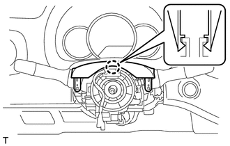
REMOVE UPPER STEERING COLUMN COVER
-
Disengage the claw and remove the upper steering column cover.
-
-
REMOVE COMBINATION SWITCH ASSEMBLY
-
Disconnect all connectors from the combination switch assembly.
-
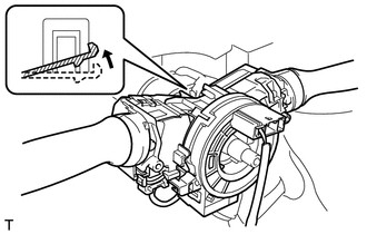
Use pliers to hold the clamp and raise the claw with a screwdriver. Remove the combination switch assembly from the steering column assembly.
-
-
REMOVE COLUMN HOLE COVER SILENCER SHEET
-
Remove the 2 clips and the column hole cover silencer sheet.
-
-
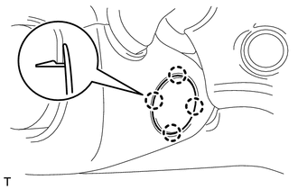
REMOVE STEERING SLIDING YOKE SUB-ASSEMBLY
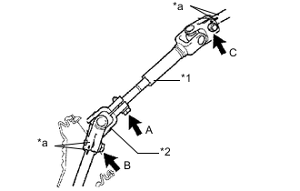
Text in Illustration *1 No. 2 Steering Intermediate Shaft Assembly *2 Steering Sliding Yoke Sub-assembly *a Matchmark
-
Place matchmarks on the No. 2 steering intermediate shaft assembly and steering column assembly.
-
Place matchmarks on the steering sliding yoke sub-assembly and steering gear assembly.
-
Loosen bolt A.
-
Loosen bolt C.
-
Remove bolt B and detach the steering sliding yoke sub-assembly from the steering gear assembly.
-
-
REMOVE BRAKE PEDAL SUPPORT SUB-ASSEMBLY (for TMC Made)
-
REMOVE BRAKE PEDAL SUPPORT SUB-ASSEMBLY (for TMMF Made)
-
REMOVE STEERING COLUMN ASSEMBLY
-
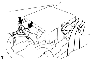
Separate the wire harness clamp from the power steering ECU assembly.
-
Disconnect the 2 steering column assembly connectors from the power steering ECU assembly.
-
Disconnect all connectors and detach all wire harness clamps from the steering column assembly.
-
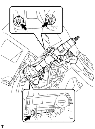
Remove the bolt, 2 nuts and the steering column assembly from the instrument panel reinforcement assembly.
-