SUPERCHARGER INSTALLATION

CAUTION / NOTICE / HINT
PROCEDURE
-
INSTALL SUPERCHARGER ASSEMBLY
Note
Do not damage the cooler condenser assembly, when installing the supercharger assembly.
-
Set a new intake manifold gasket to the cylinder head sub-assembly.
-
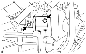
Temporarily install the supercharger bracket to the cylinder block sub-assembly with the 2 bolts.
-
Temporarily install the supercharger assembly with the bolt and a new nut.
-
Temporarily install the supercharger bracket to the supercharger assembly with the bolt.
-
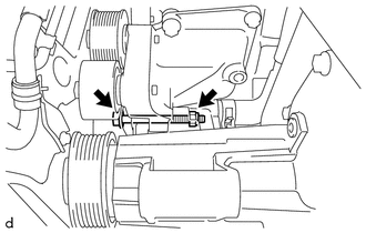
Fully tighten the bolt.
- Torque:
- 20 N*m { 204 kgf*cm, 15 ft.*lbf }
-
Fully tighten the nut.
- Torque:
- 20 N*m { 204 kgf*cm, 15 ft.*lbf }
-
Temporarily install the 3 bolts, plate washer and 2 new nuts.
-
Using SST (supercharger set bolt wrench), SST (extension wrench 13), SST (extension semideep socket 13) and 10 mm union nut wrench, tighten the 3 bolts and 2 nuts in the order shown in the illustration.
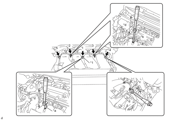
*1 Plate Washer - - *a SST (Supercharger Set Bolt Wrench) *b SST (Extension Wrench 13) and SST (Extension Semideep Socket 13) *c 10 mm Union Nut Wrench *d Torque Wrench Fulcrum Length - SST
- 09292-52010 ( 09925-04130 )
- Torque:
- Specified tightening torque
- 25 N*m { 255 kgf*cm, 18 ft.*lbf }
Tech Tips
-
Calculate the torque wrench reading when changing the fulcrum length of the torque wrench.
-
When using SST (supercharger set bolt wrench (fulcrum length of 50 mm (1.97 in.))) + torque wrench (fulcrum length of 162 mm (6.38 in.)):
19 N*m (194 kgf*cm, 14 ft.*lbf)
-
When using SST (extension wrench 13 and extension semideep socket 13 (fulcrum length of 200 mm (7.87 in.))) + torque wrench (fulcrum length of 162 mm (6.38 in.)):
11 N*m (112 kgf*cm, 8 ft.*lbf)
-
When using a 10 mm union nut wrench (fulcrum length of 22 mm (0.886 in.)) + torque wrench (fulcrum length of 162 mm (6.38 in.)):
22 N*m (224 kgf*cm, 16 ft.*lbf)
-
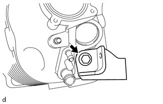
Fully tighten the bolt.
- Torque:
- 45 N*m { 459 kgf*cm, 33 ft.*lbf }
-
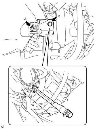
*a Torque Wrench Fulcrum Length Fully tighten the bolt (A).
- Torque:
- 25 N*m { 255 kgf*cm, 18 ft.*lbf }
-
Using a 10 mm union nut wrench, fully tighten the bolt (B).
- Torque:
- Specified tightening torque
- 25 N*m { 255 kgf*cm, 18 ft.*lbf }
Tech Tips
-
Calculate the torque wrench reading when changing the fulcrum length of the torque wrench.
-
When using a 10 mm union nut wrench (fulcrum length of 22 mm (0.886 in.)) + torque wrench (fulcrum length of 162 mm (6.38 in.)):
22 N*m (224 kgf*cm, 16 ft.*lbf)
-
Connect the ventilation hose to the supercharger assembly and slide the hose clip to secure it.
-
Connect the fuel vapor feed hose to the supercharger assembly.
-
Connect the No. 1 vacuum transmitting hose to the supercharger assembly and slide the hose clip to secure it.
-
Install the wire harness clamp bracket to the supercharger assembly with the bolt.
- Torque:
- 10 N*m { 102 kgf*cm, 7 ft.*lbf }
-
Engage the clamp to connect the engine wire to the wire harness clamp bracket.
-
-
INSTALL VACUUM SENSOR (MANIFOLD ABSOLUTE PRESSURE SENSOR)
-
INSTALL OIL LEVEL DIPSTICK GUIDE O-RING
-
Apply a light coat of the engine oil to a new oil level dipstick guide O-ring.
-
Install the oil level dipstick guide O-ring to the oil level dipstick guide sub-assembly.
-
-
INSTALL OIL LEVEL DIPSTICK GUIDE SUB-ASSEMBLY
-
Install the oil level dipstick guide sub-assembly to the supercharger assembly and oil pan sub-assembly with the bolt.
- Torque:
- 16 N*m { 163 kgf*cm, 12 ft.*lbf }
-
Engage the clamp to connect the No. 9 intercooler cooling water hose to the oil level dipstick guide sub-assembly.
-
Engage the clamp to connect the wire harness to the oil level dipstick guide sub-assembly.
-
-
INSTALL OIL LEVEL DIPSTICK SUB-ASSEMBLY
-
Install the oil level dipstick sub-assembly to the oil level dipstick guide sub-assembly.
-
-
INSTALL STARTER ASSEMBLY
-
INSTALL THROTTLE BODY WITH MOTOR ASSEMBLY
-
CONNECT NO. 7 SUB-RADIATOR HOSE
-
Connect the No. 7 sub-radiator hose to the supercharger assembly and slide the hose clip to secure it.
-
-
CONNECT NO. 4 SUB-RADIATOR HOSE
-
Connect the No. 4 sub-radiator hose to the supercharger assembly and slide the hose clip to secure it.
-
-
INSTALL FUEL INJECTOR ASSEMBLY
-
INSTALL GENERATOR ASSEMBLY
-
INSTALL RADIATOR ASSEMBLY
-
ADD COOLANT (for Intercooler)
-
INSPECT FOR COOLANT LEAK (for Intercooler)
-
INSPECT FOR FUEL LEAK