EXHAUST MANIFOLD INSTALLATION
PROCEDURE
-
INSTALL NO. 2 EXHAUST MANIFOLD HEAT INSULATOR
-
Install the No. 2 exhaust manifold heat insulator to the exhaust manifold with the 3 bolts.
- Torque:
- 12 N*m { 122 kgf*cm, 9 ft.*lbf }
-
-
INSTALL EXHAUST MANIFOLD TO HEAD GASKET
-
Install a new exhaust manifold to head gasket to the cylinder head sub-assembly.
-
-
INSTALL EXHAUST MANIFOLD
-
Temporarily install the exhaust manifold and manifold stay with 5 new nuts and the 3 bolts.
-
Tighten the 5 nuts.
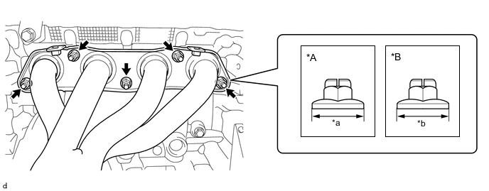
*A Type A *B Type B *a 18 mm (0.709 in.) *b 17 mm (0.669 in.) - Torque:
- Type A
- 37 N*m { 377 kgf*cm, 27 ft.*lbf }
- Type B
- 26 N*m { 265 kgf*cm, 19 ft.*lbf }
-
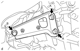
Tighten the 2 bolts (A).
- Torque:
- 43 N*m { 438 kgf*cm, 32 ft.*lbf }
-
Tighten the bolt (B).
- Torque:
- 43 N*m { 438 kgf*cm, 32 ft.*lbf }
-
-
INSTALL NO. 1 EXHAUST MANIFOLD HEAT INSULATOR
-
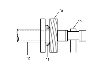
Temporarily install the No. 1 exhaust manifold heat insulator to the exhaust manifold with the 4 bolts.
-
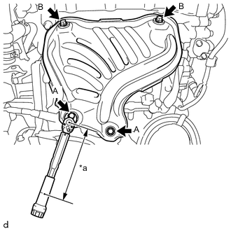
*a Torque Wrench Fulcrum Length Using a 12 mm union nut wrench, tighten the 2 bolts (A).
- Torque:
- Specified tightening torque
- 12 N*m { 122 kgf*cm, 9 ft.*lbf }
Tech Tips
-
Calculate the torque wrench reading when changing the fulcrum length of the torque wrench.
-
When using a 12 mm union nut wrench (fulcrum length of 20 mm (0.787 in.)) + torque wrench (fulcrum length of 162 mm (6.38 in.)):
11 N*m (112 kgf*cm, 8 ft.*lbf)
-
Tighten the 2 bolts (B).
- Torque:
- 12 N*m { 122 kgf*cm, 9 ft.*lbf }
-
-
INSTALL OXYGEN SENSOR
-
INSTALL FRONT DRIVE SHAFT ASSEMBLY RH
-
INSTALL FRONT EXHAUST PIPE ASSEMBLY
-
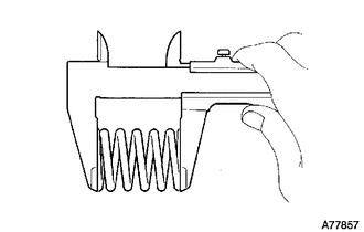
Using a vernier caliper, measure the free length of the compression springs.
Free Length of Compression Spring Compression Spring Standard Free Length Minimum Free Length Front Side 43 mm (1.69 in.) 41.5 mm (1.63 in.) Rear Side 40 mm (1.57 in.) 38.5 mm (1.52 in.) If the free length is less than the minimum, replace the compression spring.
-
Insert a new exhaust pipe gasket to the exhaust manifold as far as possible by hand.
-

*1 Exhaust Pipe Gasket *2 Exhaust Manifold *a Wooden Block *b Plastic Hammer Using a plastic hammer and a wooden block, tap in the exhaust pipe gasket until its surface is flush with the exhaust manifold.
Note
-
Install the exhaust pipe gasket in the correct direction.
-
Do not reuse the exhaust pipe gasket.
-
Do not damage the exhaust pipe gasket by dropping it, etc.
-
Do not damage the outer surface of the exhaust pipe gasket.
-
Do not push in the exhaust pipe gasket with the front exhaust pipe assembly when connecting it.
-
-
Insert a new exhaust pipe gasket to the front exhaust pipe assembly as far as possible by hand.
-
*1 Exhaust Pipe Gasket *2 Front Exhaust Pipe Assembly *a Wooden Block *b Plastic Hammer Using a plastic hammer and a wooden block, tap in the exhaust pipe gasket until its surface is flush with the front exhaust pipe assembly.
Note
-
Install the exhaust pipe gasket in the correct direction.
-
Do not reuse the exhaust pipe gasket.
-
Do not damage the exhaust pipe gasket by dropping it, etc.
-
Do not damage the outer surface of the exhaust pipe gasket.
-
Do not push in the exhaust pipe gasket with the tail exhaust pipe assembly when connecting it.
-
-
Connect the 3 exhaust pipe supports to install the front exhaust pipe assembly to the vehicle.
-
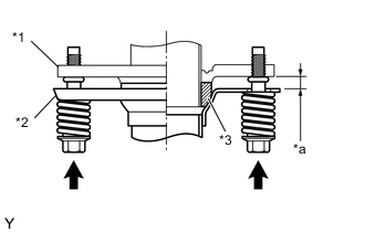
*1 Exhaust Manifold *2 Front Exhaust Pipe Assembly *3 Exhaust Pipe Gasket *a Space between Flanges: 8.5 mm (0.335 in.) Connect the front exhaust pipe assembly to the exhaust manifold with the 2 compression springs and 2 bolts.
- Torque:
- 43 N*m { 438 kgf*cm, 32 ft.*lbf }
Tech Tips
After the installation, check that the gaps between the flanges of the exhaust manifold and front exhaust pipe assembly are consistent front-to-rear and left-to-right.
-
*1 Front Exhaust Pipe Assembly *2 Tail Exhaust Pipe Assembly *3 Exhaust Pipe Gasket *a Space between Flanges: 6.5 mm (0.256 in.) Connect the front exhaust pipe assembly to the tail exhaust pipe assembly with the 2 compression springs and 2 bolts.
- Torque:
- 43 N*m { 438 kgf*cm, 32 ft.*lbf }
Tech Tips
After the installation, check that the gaps between the flanges of the front exhaust pipe assembly and tail exhaust pipe assembly are consistent front-to-rear and left-to-right.
-
Pass the connector through the hole to the inside of the vehicle and install the grommet of the heated oxygen sensor.
-
Connect the heated oxygen sensor connector.
-
Return the front floor carpet assembly.
-
-
INSTALL REAR CONSOLE BOX ASSEMBLY
-
INSTALL FRONT FLOOR CENTER BRACE
-
INSPECT FOR EXHAUST GAS LEAK
If gas is leaking, tighten the areas necessary to stop the leak. Replace damaged parts as necessary.
-
Perform Inspection After Repair after repairing an exhaust gas leak.
-