EXHAUST MANIFOLD W/ TURBOCHARGER INSTALLATION
PROCEDURE
-
INSTALL STUD BOLT
Tech Tips
Only perform this procedure when replacement of the stud bolt is necessary.
-
Using "TORX" socket wrench E10, install the 2 stud bolts to the turbocharger sub-assembly.
- Torque:
- 23 N*m { 229 kgf*cm, 17 ft.*lbf }
-
Using "TORX" socket wrench E5, install the 2 stud bolts to the turbocharger sub-assembly.
- Torque:
- 7.0 N*m { 67 kgf*cm, 58 in.*lbf }
-
Using a double nut, install the 3 stud bolts to the turbocharger sub-assembly.
- Torque:
- 15 N*m { 148 kgf*cm, 11 ft.*lbf }
-
Using "TORX" socket wrench E6, install the 3 stud bolts to the turbocharger sub-assembly.
- Torque:
- 3.0 N*m { 31 kgf*cm, 27 in.*lbf }
-
Using "TORX" socket wrench E10, install the stud bolt to the turbocharger sub-assembly.
- Torque:
- 22 N*m { 224 kgf*cm, 16 ft.*lbf }
-
Using "TORX" socket wrench E10, install the stud bolt to the exhaust manifold.
- Torque:
- 22 N*m { 224 kgf*cm, 16 ft.*lbf }
-
-
INSTALL EXHAUST MANIFOLD (w/o DPF)
-
Install a new exhaust manifold to head gasket to the cylinder head sub-assembly.
-
Install the exhaust manifold to the cylinder head sub-assembly with the 8 nuts.
- Torque:
- 43 N*m { 438 kgf*cm, 32 ft.*lbf }
-
-
INSTALL EXHAUST MANIFOLD (w/ DPF)
-
Install a new exhaust manifold to head gasket to the cylinder head sub-assembly.
-
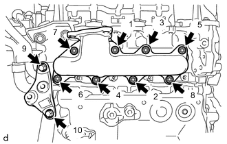
Temporarily install the No. 2 manifold support bracket to the cylinder head sub-assembly and cylinder block sub-assembly with the 2 bolts.
-
Temporarily install the exhaust manifold to the cylinder head sub-assembly with the 8 nuts.
-
Fully tighten the 2 bolts and 8 nuts in the sequence shown in the illustration.
- Torque:
- Bolt
- 37 N*m { 377 kgf*cm, 27 ft.*lbf }
- Nut
- 43 N*m { 438 kgf*cm, 32 ft.*lbf }
-
-
INSTALL COMPRESSOR INLET ELBOW SUB-ASSEMBLY
-
Install a new compressor inlet gasket to the compressor inlet elbow sub-assembly.
-
Install the compressor inlet elbow sub-assembly to the turbocharger sub-assembly with the 3 nuts.
- Torque:
- 9.0 N*m { 92 kgf*cm, 80 in.*lbf }
-
-
INSTALL TURBOCHARGER SUB-ASSEMBLY
-
Install a new No. 1 turbo oil outlet gasket to the cylinder block sub-assembly.
-
Temporarily install the turbo oil inlet pipe sub-assembly to the cylinder block sub-assembly with the 2 nuts.
-
Install a new turbo oil inlet gasket to the turbocharger sub-assembly.
-
Install a new turbo to exhaust manifold gasket to the exhaust manifold.
-
Install the turbocharger sub-assembly to the exhaust manifold with the 3 nuts.
- Torque:
- 53 N*m { 540 kgf*cm, 39 ft.*lbf }
Note
-
When installing the turbocharger sub-assembly, do not hold it by the electric actuator rod.
-
Simultaneously connect the turbo oil inlet pipe sub-assembly, taking care to ensure that the gasket does not fall off.
-
Connect the 2 turbocharger sub-assembly connectors.
-
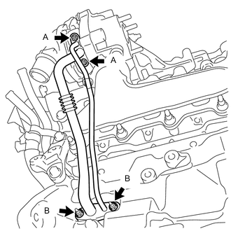
Connect the turbo oil inlet pipe sub-assembly to the turbocharger sub-assembly with the 2 nuts (A).
- Torque:
- 11 N*m { 112 kgf*cm, 8 ft.*lbf }
-
Fully tighten the 2 nuts (B).
- Torque:
- 9.0 N*m { 92 kgf*cm, 80 in.*lbf }
-
-
INSTALL MANIFOLD STAY
-
Install the manifold stay to the turbocharger sub-assembly and cylinder block sub-assembly with the 2 bolts.
- Torque:
- 37 N*m { 377 kgf*cm, 27 ft.*lbf }
-
-
INSTALL TURBOCHARGER STAY
-
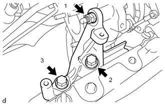
Temporarily install the turbocharger stay to the turbocharger sub-assembly and cylinder head sub-assembly with the 2 bolts and nut.
-
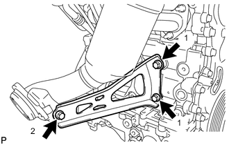
Fully tighten the 2 bolts and nut in the sequence shown in the illustration.
- Torque:
- 37 N*m { 377 kgf*cm, 27 ft.*lbf }
-
-
INSTALL NO. 1 TURBO WATER PIPE SUB-ASSEMBLY (w/ DPF)
-
Install a new gasket and No. 1 turbo water pipe sub-assembly to the turbocharger sub-assembly with the 4 bolts.
- Torque:
- 11 N*m { 112 kgf*cm, 8 ft.*lbf }
-
-
INSTALL NO. 2 TURBO WATER HOSE (w/ DPF)
-
Connect the No. 2 turbo water hose to the No. 1 turbo water pipe sub-assembly and slide the hose clip to secure it.
-
-
INSTALL NO. 1 TURBO WATER HOSE (w/ DPF)
-
Connect the No. 1 turbo water hose to the No. 1 turbo water pipe sub-assembly and slide the hose clip to secure it.
-
-
INSTALL NO. 1 AIR HOSE (w/o DPF)
-
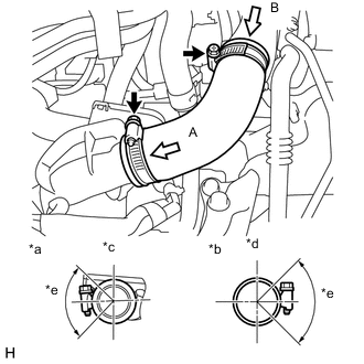
Text in Illustration *a View A *b View B *c Upper Side *d Rear Side *e Clamp installation range Install the No. 1 air hose to the turbocharger sub-assembly and No. 1 air tube and tighten the 2 hose clamps.
- Torque:
- 6.0 N*m { 61 kgf*cm, 53 in.*lbf }
-
-
INSTALL NO. 1 AIR CLEANER HOSE
-
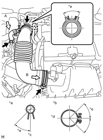
Text in Illustration *a View A *b View B *c Front Side *d Rear Side *e Clamp installation range Install the No. 1 air cleaner hose to the compressor inlet elbow sub-assembly and slide the hose clip to secure it.
-
Connect the ventilation hose to the cylinder head cover sub-assembly and slide the hose clip to secure it.
-
Engage the clamp to connect the No. 1 fuel hose sub-assembly to the No. 1 air cleaner hose.
-
Connect the No. 1 air cleaner hose to the air cleaner cap and tighten the hose clamp.
- Torque:
- 3.0 N*m { 31 kgf*cm, 27 in.*lbf }
-
-
INSTALL EXHAUST MANIFOLD CONVERTER SUB-ASSEMBLY (w/ DPF)
-
TEMPORARILY TIGHTEN EXHAUST MANIFOLD CONVERTER SUB-ASSEMBLY (w/o DPF)
-
Install a new turbine outlet elbow gasket to the turbocharger sub-assembly.
-
Temporarily install the exhaust manifold converter sub-assembly to the turbocharger sub-assembly with 3 new nuts.
-
-
TEMPORARILY TIGHTEN MANIFOLD SUPPORT BRACKET (w/o DPF)
-
Temporarily install the manifold support bracket to the exhaust manifold converter sub-assembly with the 3 bolts.
-
-
TIGHTEN EXHAUST MANIFOLD CONVERTER SUB-ASSEMBLY (w/o DPF)
-
Tighten the 3 nuts.
- Torque:
- 26 N*m { 265 kgf*cm, 19 ft.*lbf }
-
-
TIGHTEN MANIFOLD SUPPORT BRACKET (w/o DPF)
-
Tighten the 3 bolts in the sequence shown in the illustration.
- Torque:
- 37 N*m { 375 kgf*cm, 27 ft.*lbf }
-
-
INSTALL NO. 1 TURBO INSULATOR (w/o DPF)
-
INSTALL WIRE HARNESS CLAMP BRACKET (w/o DPF)
-
INSTALL NO. 2 ENGINE COVER BRACKET (w/o DPF)
-
INSTALL NO. 1 ENGINE COVER (w/o DPF)
-
INSTALL OUTER COWL TOP PANEL (w/o DPF)
-
INSTALL INNER COWL TOP TO COWL BRACE (w/o DPF)
-
INSTALL FRONT NO. 1 VENTILATOR SEAL (w/o DPF)
-
INSTALL FRONT AIR SHUTTER SEAL RH (w/o DPF)
-
INSTALL WINDSHIELD WIPER MOTOR AND LINK ASSEMBLY (w/o DPF)
-
INSTALL FRONT EXHAUST PIPE ASSEMBLY (w/o DPF)
-
INSPECT FOR EXHAUST GAS LEAK (w/o DPF)
-
CLEAR DTC (P0046)
-
When a new turbocharger is installed, DTC P0046 is likely to occur. It should be cleared by the special method Click here.
-