EXHAUST MANIFOLD INSTALLATION
PROCEDURE
-
INSTALL EGR PIPE GASKET
-
Install a new EGR pipe gasket to the EGR pipe assembly.
-
-
INSTALL EXHAUST MANIFOLD GASKET
-
Install a new exhaust manifold gasket to the exhaust cooler assembly.
-
-
INSTALL EXHAUST MANIFOLD CONVERTER SUB-ASSEMBLY
-
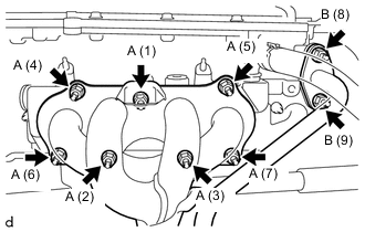
Temporarily install the exhaust manifold converter sub-assembly to the exhaust cooler assembly and EGR pipe assembly with 7 new nuts (A) and 2 nuts (B).
-
Tighten the 7 nuts (A) and 2 nuts (B) in the order shown in the illustration.
- Torque:
- 26 N*m { 265 kgf*cm, 19 ft.*lbf }
-
-
INSTALL MANIFOLD STAY
-
Temporarily install the manifold stay to the exhaust manifold converter sub-assembly and cylinder block sub-assembly with the bolt and a new nut.
-
Tighten the bolt and nut in the order shown in the illustration.
- Torque:
- Bolt
- 40 N*m { 408 kgf*cm, 30 ft.*lbf }
- Nut
- 21 N*m { 214 kgf*cm, 15 ft.*lbf }
-
-
INSTALL NO. 2 EXHAUST MANIFOLD HEAT INSULATOR
-
Install the No. 2 exhaust manifold heat insulator to the exhaust manifold converter sub-assembly with the 3 bolts.
- Torque:
- 10 N*m { 102 kgf*cm, 7 ft.*lbf }
-
-
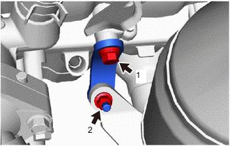
INSTALL AIR FUEL RATIO SENSOR
-
CONNECT FRONT EXHAUST PIPE ASSEMBLY
-
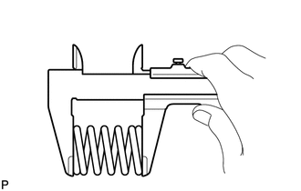
Using a vernier caliper, measure the free length of the compression spring.
Free Length of Compression Spring Standard Length Minimum Length 43 mm (1.69 in.) 41.5 mm (1.63 in.) If the length is not as specified, replace the compression spring.
-
Insert a new exhaust pipe gasket to the exhaust manifold converter sub-assembly as far as possible by hand.
-
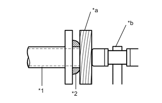
*1 Exhaust Manifold Converter Sub-assembly *2 Exhaust Pipe Gasket *a Wooden Block *b Plastic Hammer Using a plastic hammer and a wooden block, tap in the exhaust pipe gasket until its surface is flush with the exhaust manifold converter sub-assembly.
Note
-
Install the exhaust pipe gasket in the correct direction.
-
Do not reuse the exhaust pipe gasket.
-
Do not damage the exhaust pipe gasket by dropping it, etc.
-
Do not damage the outer surface of the exhaust pipe gasket.
-
Do not push in the exhaust pipe gasket with the front exhaust pipe assembly when connecting it.
-
-
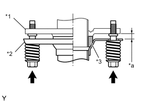
*1 Exhaust Manifold Converter Sub-assembly *2 Front Exhaust Pipe Assembly *3 Exhaust Pipe Gasket *a Space between flanges: 8.5 mm (0.335 in.) Install the front exhaust pipe assembly to the exhaust manifold converter sub-assembly with the 2 compression springs and 2 bolts.
- Torque:
- 43 N*m { 438 kgf*cm, 32 ft.*lbf }
Tech Tips
After the installation, check that the gaps between the flanges of the exhaust manifold converter sub-assembly and front exhaust pipe assembly are consistent front-to-rear and left-to-right.
-
Engage the clamp to connect the heated oxygen sensor wire to the wire harness clamp bracket.
-
Connect the heated oxygen sensor connector.
-
-
INSTALL NO. 1 EXHAUST MANIFOLD HEAT INSULATOR
-
Install the No. 1 exhaust manifold heat insulator to the exhaust manifold converter sub-assembly with the 2 bolts and 2 nuts.
- Torque:
- 7.5 N*m { 76 kgf*cm, 66 in.*lbf }
-
-
INSTALL OIL LEVEL DIPSTICK GUIDE O-RING
-
Apply a light coat of the engine oil to a new oil level dipstick guide O-ring.
-
Install the oil level dipstick guide O-ring to the oil level dipstick guide.
-
-
INSTALL OIL LEVEL DIPSTICK GUIDE
-
Install the oil level dipstick guide to the oil pan sub-assembly and cylinder head cover sub-assembly with the bolt.
- Torque:
- 10 N*m { 102 kgf*cm, 7 ft.*lbf }
Note
Prevent the oil level dipstick guide O-ring from being cut or caught during installation.
-
-
INSTALL OIL LEVEL DIPSTICK SUB-ASSEMBLY
-
Install the oil level dipstick sub-assembly to the oil level dipstick guide.
-
-
INSTALL NO. 1 ENGINE COVER
-
INSPECT FOR EXHAUST GAS LEAK
Tech Tips
Perform Inspection After Repairs after repairing or replacing the exhaust system.