CANISTER REMOVAL

PROCEDURE
-
PRECAUTION
Note
-
Keep fuel away from rubber or leather parts.
-
After turning the engine switch off, waiting time may be required before disconnecting the cable from the negative (-) battery terminal. Therefore, make sure to read the disconnecting the cable from the negative (-) battery terminal notices before proceeding with work.
-
-
REMOVE DECK BOARD ASSEMBLY
-
REMOVE SPARE WHEEL COVER
-
REMOVE REAR SEAT ASSEMBLY LH
-
REMOVE REAR SEAT ASSEMBLY RH
-
REMOVE REAR SEATBACK CENTER HINGE SUB-ASSEMBLY
-
DISCHARGE FUEL SYSTEM PRESSURE
-
REMOVE REAR FLOOR SERVICE HOLE COVER
-
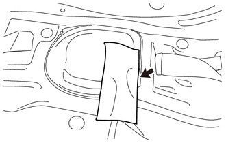
Remove the wiring harness protector from the rear floor service hole cover and vehicle floor.
-
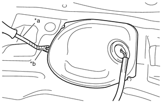
*a Clip Remover *b Protective Tape Using a clip remover with its tip wrapped in protective tape, remove the rear floor service hole cover from the vehicle floor.
-
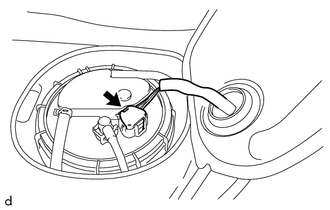
Disconnect the fuel suction tube with pump and gauge assembly connector.
-
-
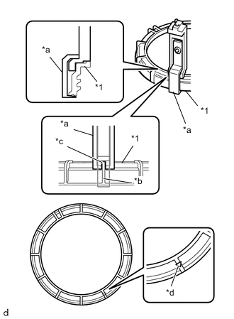
DISCONNECT FUEL TANK MAIN TUBE SUB-ASSEMBLY
-
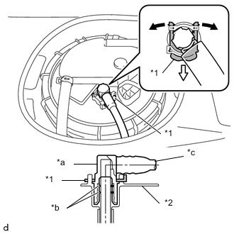
*1 Tube Joint Clip *2 Fuel Suction Plate Sub-assembly *a Fuel Tube Joint *b O-ring *c Nylon Tube 
Widen 
Pull Out Spread the tip of the tube joint clip and pull it out in the direction of the arrow.
-
Disconnect the fuel tank main tube sub-assembly from the fuel suction plate sub-assembly.
Note
-
Remove any dirt or foreign matter on the fuel tube joint before performing this work.
-
Do not allow any scratches or foreign matter to get on the parts when disconnecting them as the fuel tube joint has O-rings that seal the fuel pipe.
-
Only disconnect the fuel tube joint by hand.
-
Do not forcibly bend, twist or turn the fuel tank main tube sub-assembly.
-
Protect the disconnected part by covering it with a plastic bag after disconnecting the fuel tube joint.
-
If the fuel tube joint and fuel suction plate sub-assembly are stuck, push and pull to release them.
-
-
-
DISCONNECT NO. 2 FUEL EMISSION TUBE
-
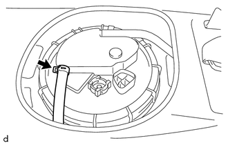
Slide the hose clip and disconnect the No. 2 fuel emission tube from the fuel suction tube with pump and gauge assembly.
-
-
DISCONNECT NO. 1 CANISTER OUTLET HOSE SUB-ASSEMBLY
-
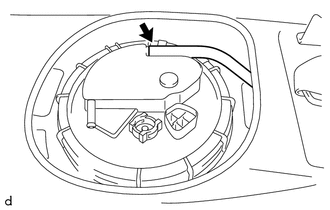
Disconnect the No. 1 canister outlet hose sub-assembly from the fuel suction tube with pump and gauge assembly.
-
-
REMOVE FUEL PUMP GAUGE RETAINER
Note
Before performing these procedures, first cover the connectors and tube joints of the fuel suction tube with pump and gauge assembly with vinyl tape and then clean away any mud or other substances that may be adhering in order to prevent foreign matter from contaminating the fuel system.
-
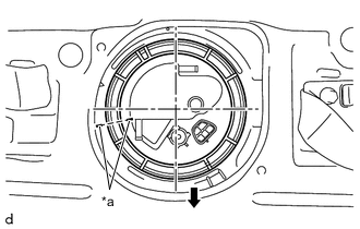
*a Paint Mark Front Side of Vehicle Place paint marks on the fuel suction tube with pump and gauge assembly and vehicle body as shown in the illustration.
Note
-
The fuel suction tube with pump and gauge assembly has a protrusion that engage with a notch on the fuel tank assembly to ensure correct alignment and to prevent the fuel suction tube with pump and gauge assembly from turning during installation and removal of the fuel pump gauge retainer.
-
If the fuel pump gauge retainer is turned with the fuel suction tube with pump and gauge assembly misaligned, the fuel suction tube with pump and gauge assembly will turn with the fuel pump gauge retainer and may be damaged.
-
The paint marks are used to ensure that the fuel suction tube with pump and gauge assembly does not turn with the fuel pump gauge retainer.
-
-
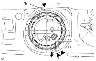
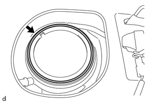
*a Fully Tightened Mark on Fuel Tank Assembly *b Start of Threads on Fuel Tank Assembly *c Copy of Fully Tightened Mark *d Copy of Start of Threads Mark Front Side of Vehicle Copy the start of threads mark and fully tightened marks from the fuel tank assembly to the vehicle body in order to record their locations.
-
Install SST to the fuel pump gauge retainer.
-
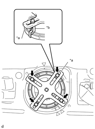
*1 Fuel Pump Gauge Retainer *a SST (Claw Set) *b Protrusion *c Notch *d Do not install SST (Claw Set) Set 4 SST (claw set) to the fuel pump gauge retainer.
- SST
- 09808-14031 ( 09808-01080, 09808-01090, 09808-01100 )
Note
-
Align the notch of SST (claw set) with the protrusion of the fuel pump gauge retainer.
-
Do not install SST (claw set) to the start of threads location of the fuel pump gauge retainer.
-
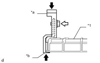
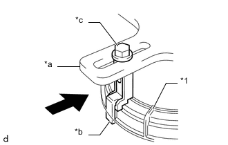
*1 Fuel Pump Gauge Retainer *a SST (Claw Set) *b Hook Push SST (Bolt) Push SST (claw set) against the fuel pump gauge retainer and tighten SST (bolt).
-
*a SST (Plate) *b SST (Claw Set) SST (Bolt) Temporarily install SST (plate) to SST (claw set) with 4 SST (bolt).
- SST
- 09808-14031 ( 09808-01030, 09808-01090 )
-
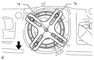
*a Center Point of Fuel Pump Gauge Retainer *b SST (Plate) Front Side of Vehicle Adjust the position of SST (claw set) so that the hole in SST (plate) for installing SST (handle) is in the center of the fuel pump gauge retainer.
-
*1 Fuel Pump Gauge Retainer *a SST (Plate) *b SST (Claw Set) *c SST (Bolt) Press Press SST (claw set) against the rib of the fuel pump gauge retainer and tighten SST (bolt).
-
Install SST (handle) to SST (plate).
- SST
- 09808-14031 ( 09808-01010, 09808-01020 )
-
-
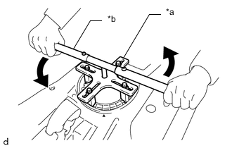
*a SST (Plate) *b SST (Handle) Loosen Slowly loosen the fuel pump gauge retainer by approximately 90°.
Note
Do not spin SST too fast or use an impact wrench as this may result in damage to components.
-
While one person loosens the fuel pump gauge retainer, have another person press down the rising fuel suction tube with pump and gauge assembly, securely insert the protrusion of the fuel suction tube with pump and gauge assembly into the groove of the fuel tank assembly, and then remove the fuel pump gauge retainer while making sure that the fuel suction tube with pump and gauge assembly is properly aligned.
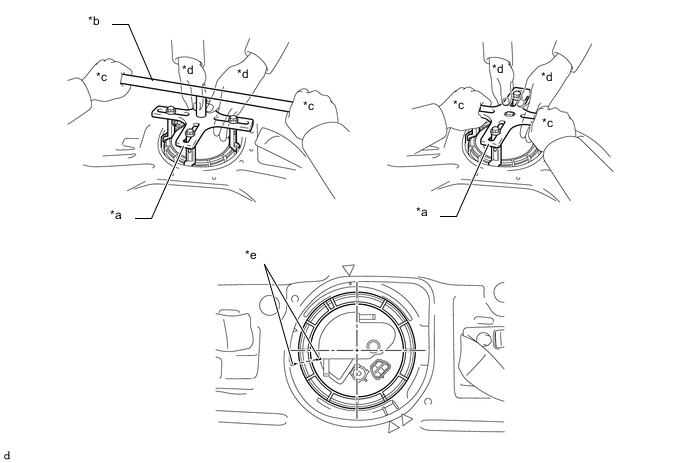
*a SST (Plate) *b SST (Handle) *c One Person in Charge of Loosening *d One Person in Charge of Pressing Down *e Paint Mark - - Note
-
The fuel suction tube with pump and gauge assembly is pressed against the underside of the fuel tank assembly by a spring, and the constant upward pressure applied by this spring causes the fuel suction tube with pump and gauge assembly to rise up.
-
If the fuel pump gauge retainer is turned while the fuel suction tube with pump and gauge assembly and fuel tank assembly are not correctly aligned, the fuel suction tube with pump and gauge assembly will move with the fuel pump gauge retainer, and the fuel suction tube with pump and gauge assembly and fuel tank assembly may both be damaged.
-
Do not turn the fuel pump gauge retainer if the paint marks become misaligned.
-
-
-
REMOVE FUEL SUCTION TUBE WITH PUMP AND GAUGE ASSEMBLY
-
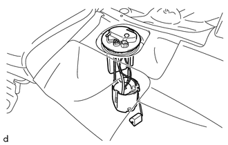
Pull out the arm portion of the fuel sender gauge assembly, and remove the fuel suction tube with pump and gauge assembly from the fuel tank assembly.
Note
-
Be careful not to bend the arm of the fuel sender gauge assembly.
-
When installing or removing the fuel suction tube with pump and gauge assembly, be careful of fuel splashing.
-
-
-
REMOVE FUEL SUCTION TUBE SET GASKET
-
Remove the fuel suction tube set gasket from the fuel tank assembly.
-
-
REMOVE FUEL SENDER GAUGE ASSEMBLY
-
REMOVE FUEL PUMP
-
REMOVE FUEL PRESSURE REGULATOR ASSEMBLY