EXHAUST MANIFOLD INSTALLATION
PROCEDURE
-
INSTALL NO. 1 MANIFOLD CONVERTER INSULATOR
-
Install the No. 1 manifold converter insulator onto the exhaust manifold converter sub-assembly with the 2 bolts.
- Torque:
- 8.5 N*m { 87 kgf*cm, 75 in.*lbf }
-
-
INSTALL EXHAUST MANIFOLD CONVERTER SUB-ASSEMBLY
-
Install the new exhaust manifold to head gasket and inlet EGR gasket onto the cylinder head sub-assembly.
-
Temporarily install the exhaust manifold converter sub-assembly onto the cylinder head sub-assembly with the 2 bolts and 4 nuts.
-
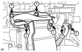
Tighten the 2 bolts and 4 nuts in the order shown in the illustration.
- Torque:
- 28 N*m { 286 kgf*cm, 21 ft.*lbf }
-
-
INSTALL MANIFOLD STAY
-
Temporarily install the manifold stay with the 2 bolts.
-
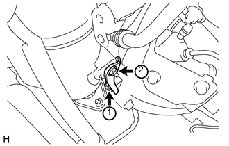
Tighten the 2 bolts in the order shown in the illustration.
- Torque:
- 24 N*m { 245 kgf*cm, 18 ft.*lbf }
-
-
INSTALL EGR INLET EXHAUST MANIFOLD PLATE
-
Install the EGR inlet exhaust manifold plate onto the No. 1 water by-pass pipe with the 2 bolts.
- Torque:
- 18 N*m { 184 kgf*cm, 13 ft.*lbf }
-
-
INSTALL HEATED OXYGEN SENSOR
-
INSTALL FRONT EXHAUST PIPE ASSEMBLY
-
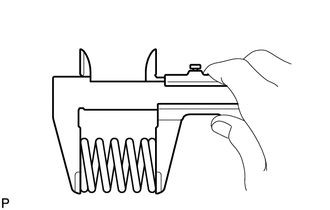
Using a vernier caliper, measure the free length of the compression spring.
Minimum Length 41.5 mm (1.634 in.) Tech Tips
If the length is not as specified, replace the compression spring.
-
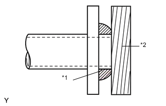
Text in Illustration *1 Exhaust Pipe Gasket *2 Wooden Block Using a plastic hammer and a wooden block, tap in a new exhaust pipe gasket until its surface is flush with the exhaust manifold converter sub-assembly.
Note
-
Install the gasket in the correct direction.
-
Do not reuse the gasket.
-
Do not damage the gasket by dropping it, etc.
-
Do not damage the outer surface of the gasket.
-
Do not push in the gasket with the exhaust pipe when connecting it.
-
-
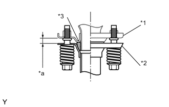
Text in Illustration *1 Exhaust Manifold Converter Sub-assembly *2 Front Exhaust Pipe Assembly *3 Exhaust Pipe Gasket *a Space between flanges: 8.5 mm (0.335 in.) Install the front exhaust pipe assembly to the exhaust manifold converter sub-assembly with the 2 compression springs and 2 bolts.
- Torque:
- 43 N*m { 438 kgf*cm, 32 ft.*lbf }
Note
After the installation, check that the gaps between the flanges of the exhaust manifold and front exhaust pipe assembly are consistent front-to-rear and left-to-right.
-
Engage the 3 clamps and connect the No. 2 heated oxygen sensor wire to the fan shroud.
-
Connect the connector of the No. 2 heated oxygen sensor.
-
-
INSPECT FOR EXHAUST GAS LEAK