INTAKE MANIFOLD INSTALLATION
PROCEDURE
-
INSTALL EGR VALVE GASKET
-
INSTALL EGR VALVE ASSEMBLY
-
INSTALL NO. 2 INTAKE MANIFOLD TO HEAD GASKET
-
Install a new No. 2 intake manifold to head gasket to the cylinder head sub-assembly.
-
-
INSTALL NO. 1 INTAKE MANIFOLD INSULATOR
-
Temporarily install the No. 1 intake manifold insulator to the EGR valve assembly with the 2 bolts and nut.
Tech Tips
Fully tighten the 2 bolts and nut when installing the intake manifold.
-
-
INSTALL NO. 1 INTAKE MANIFOLD TO HEAD GASKET
-
Install a new No. 1 intake manifold to head gasket to the intake manifold.
-
-
INSTALL VACUUM HOSE CLAMP
-
for LHD:
-
Engage the clamp to install the vacuum hose clamp to the intake manifold.
-
-
for RHD:
-
Engage the 2 clamps to install the 2 vacuum hose clamps to the intake manifold.
-
-
-
INSTALL INTAKE MANIFOLD
-
Temporarily install the intake manifold to the cylinder head sub-assembly with the 2 bolts and 2 nuts.
-
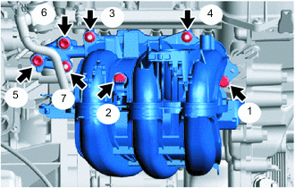
Tighten the 4 bolts and 3 nuts in the order shown in the illustration.
- Torque:
- 30 N*m { 306 kgf*cm, 22 ft.*lbf }
-
Install the fuel hose bracket to the intake manifold with the bolt.
- Torque:
- 8.0 N*m { 82 kgf*cm, 71 in.*lbf }
-
Install the wire harness clamp bracket to the intake manifold with the bolt.
- Torque:
- 8.4 N*m { 86 kgf*cm, 74 in.*lbf }
-
Engage the 3 clamps to connect the wire harness to the intake manifold and wire harness clamp bracket.
-
Engage the 4 clamps to connect the No. 1 water by-pass hose and No. 2 water by-pass hose to the intake manifold.
-
Engage the clamp to connect the fuel tube sub-assembly to the fuel hose clamp.
-
-
CONNECT NO. 2 FUEL VAPOR FEED HOSE
-
Connect the No. 2 fuel vapor feed hose to the intake manifold and slide the hose clip to secure it.
-
-
CONNECT VACUUM HOSE ASSEMBLY
-
for RHD:
-
Engage the clamp to connect the vacuum hose assembly to the vacuum hose clamp.
-
-
Engage the clamp to connect the vacuum hose assembly to the vacuum hose clamp.
-
Align the vacuum hose assembly connector with the intake manifold, and push them together until the vacuum hose assembly connector makes "click" sound.
Note
After connecting the vacuum hose assembly connector and intake manifold, check that they are securely connected by trying to pull them apart.
-
-
INSTALL MANIFOLD ABSOLUTE PRESSURE SENSOR
-
INSTALL THROTTLE BODY WITH MOTOR ASSEMBLY
-
INSTALL OUTER COWL TOP PANEL (for LHD)
-
INSTALL OUTER COWL TOP PANEL (for RHD)
-
INSTALL INNER COWL TOP TO COWL BRACE (for LHD)
-
INSTALL INNER COWL TOP TO COWL BRACE (for RHD)
-
INSTALL FRONT AIR SHUTTER SEAL RH (for LHD)
-
INSTALL FRONT AIR SHUTTER SEAL RH (for RHD)
-
INSTALL FRONT NO. 1 VENTILATOR SEAL (for LHD)
-
INSTALL FRONT NO. 1 VENTILATOR SEAL (for RHD)
-
INSTALL WINDSHIELD WIPER MOTOR AND LINK ASSEMBLY
-
INSPECT INTAKE SYSTEM