EXHAUST GAS TEMPERATURE SENSOR(for Lower Side) INSTALLATION
PROCEDURE
-
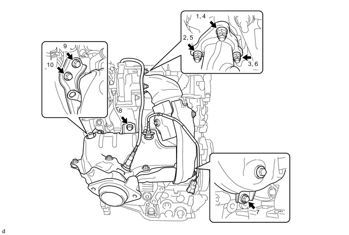
INSTALL NO. 2 EXHAUST GAS TEMPERATURE SENSOR
-
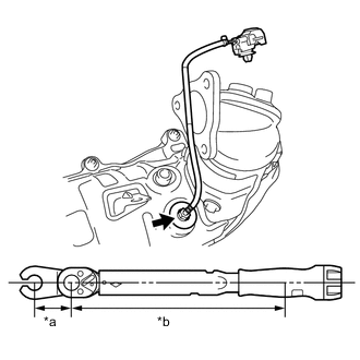
Text in Illustration *a Union Nut Wrench Fulcrum Length *b Torque Wrench Fulcrum Length Using a union nut wrench 14 mm, install the No. 2 exhaust gas temperature sensor to the exhaust manifold.
- Torque:
- Specified tightening torque
- 30 N*m { 306 kgf*cm, 22 ft.*lbf }
Tech Tips
-
Calculate the torque wrench reading when changing the fulcrum length of the torque wrench.
-
When a union nut wrench 14 mm (fulcrum length of 30 mm (1.18 in.)) + torque wrench (fulcrum length of 180 mm (7.09 in.)): 26 N*m (265 kgf*cm, 19 ft.*lbf)
-
-
INSTALL AIR FUEL RATIO SENSOR (for Sensor 2)
-
INSTALL NO. 1 PIPE
-
Temporarily install the No. 1 pipe to the exhaust manifold.
-
Connect the No. 1 pipe to the exhaust manifold with the bolt.
- Torque:
- 21 N*m { 214 kgf*cm, 15 ft.*lbf }
-
Tighten the No. 1 pipe.
- Torque:
- Specified tightening torque
- 48 N*m { 489 kgf*cm, 35 ft.*lbf }
Tech Tips
-
Calculate the torque wrench reading when changing the fulcrum length of the torque wrench.
-
When a union nut wrench 14 mm (fulcrum length of 25 mm (0.98 in.)) + torque wrench (fulcrum length of 180 mm (7.09 in.)): 42 N*m (428 kgf*cm, 31 ft.*lbf)
-
-
INSTALL EXHAUST MANIFOLD
-
Install a new gasket to the turbocharger sub-assembly.
-
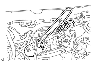
As shown in the illustration, fix the exhaust manifold to the vehicle using a rope or similar.
Note
Make sure to perform this step in order to prevent the exhaust manifold from falling.
-
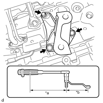
Text in Illustration *a Torque Wrench Fulcrum Length *b Offset Wrench Fulcrum Length Temporarily install the No. 1 converter support bracket to the cylinder block sub-assembly with the 3 bolts.
-
Using a 12 x 14 mm offset wrench and a 12 mm hexagon socket wrench, fully tighten the bolt A.
- Torque:
- Specified tightening torque
- 37 N*m { 377 kgf*cm, 27 ft.*lbf }
Tech Tips
-
Calculate the torque wrench reading when changing the fulcrum length of the torque wrench.
-
When using a 12 x 14 mm offset wrench and a 12 mm hexagon socket wrench (fulcrum length of 206 mm (8.11 in.)) + torque wrench (fulcrum length of 180 mm (7.09 in.)): 17 N*m (173 kgf*cm, 13 ft.*lbf)
-
Fully tighten the 2 bolts B.
- Torque:
- 37 N*m { 377 kgf*cm, 27 ft.*lbf }
-
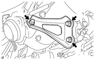
Temporarily install the exhaust manifold to the turbocharger sub-assembly, No. 1 converter support bracket, manifold stay and No. 2 converter support bracket with the 4 bolts and 3 new nuts.
-
Fully tighten the 4 bolts and 3 nuts, in the sequence shown in the illustration.
- Torque:
- Bolt
- 37 N*m { 377 kgf*cm, 27 ft.*lbf }
- Nut
- 26 N*m { 265 kgf*cm, 19 ft.*lbf }
-
-
INSTALL DRIVE SHAFT HEAT INSULATOR SUB-ASSEMBLY
-
Install the drive shaft heat insulator sub-assembly to the No. 1 converter support bracket with the 2 nuts.
- Torque:
- 18 N*m { 179 kgf*cm, 13 ft.*lbf }
-
-
INSTALL NO. 4 CONVERTER SUPPORT BRACKET
-
Install the No. 4 converter support bracket to the exhaust manifold and No. 1 converter support bracket with the 3 bolts, in the sequence shown in the illustration.
- Torque:
- 37 N*m { 377 kgf*cm, 27 ft.*lbf }
-
-
INSTALL FRONT SUSPENSION CROSSMEMBER SUB-ASSEMBLY
-
INSTALL NO. 5 CONVERTER SUPPORT BRACKET
-
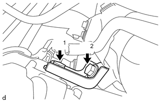
Install the No. 5 converter support bracket to the exhaust manifold and cylinder block sub-assembly with the 2 bolts, in the sequence shown in the illustration.
- Torque:
- 37 N*m { 377 kgf*cm, 27 ft.*lbf }
-
-
INSTALL NO. 2 PIPE
-
Temporarily install the No. 2 pipe to the exhaust manifold.
-
Connect the No. 2 pipe to the manifold stay with the bolt.
- Torque:
- 21 N*m { 214 kgf*cm, 15 ft.*lbf }
-
Tighten the No. 2 pipe.
- Torque:
- Specified tightening torque
- 30 N*m { 306 kgf*cm, 22 ft.*lbf }
Tech Tips
-
Calculate the torque wrench reading when changing the fulcrum length of the torque wrench.
-
When a union nut wrench 14 mm (fulcrum length of 25 mm (0.98 in.)) + torque wrench (fulcrum length of 180 mm (7.09 in.)): 26 N*m (265 kgf*cm, 19 ft.*lbf)
-
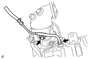
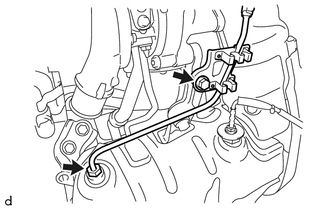
Engage the 2 clamps to connect the air fuel ratio sensor wire to the No. 2 pipe.
-
Engage the clamp to connect the No. 2 exhaust gas temperature sensor wire to the No. 2 pipe.
-
-
INSTALL TURBO INSULATOR
-
Install the turbo insulator to the turbocharger sub-assembly and exhaust manifold with the 3 bolts.
- Torque:
- 7.0 N*m { 71 kgf*cm, 62 in.*lbf }
-
Engage the 2 clamps to connect the air fuel ratio sensor wire and No. 2 exhaust gas temperature sensor wire to the turbo insulator.
-
-
INSTALL EXHAUST GAS TEMPERATURE SENSOR
-
INSTALL AIR FUEL RATIO SENSOR (for Sensor 1)
-
INSTALL SENSOR BRACKET
-
Install the sensor bracket to the cylinder head cover sub-assembly with the 2 bolts.
- Torque:
- 11 N*m { 112 kgf*cm, 8 ft.*lbf }
-
-
INSTALL NO. 2 ENGINE COVER BRACKET
-
Install the No. 2 engine cover bracket to the sensor bracket and wiring harness clamp bracket with the bolt and 2 nuts.
- Torque:
- 11 N*m { 112 kgf*cm, 8 ft.*lbf }
-
-
INSTALL NO. 1 AIR TUBE
-
INSTALL NO. 2 AIR HOSE
-
INSTALL BATTERY CARRIER (for LHD)
-
INSTALL BATTERY CARRIER (for RHD)
-
INSTALL BATTERY TRAY
-
INSTALL BATTERY
-
CONNECT NO. 1 HOSE TO HOSE TUBE (for LHD)
-
Connect the No. 2 hose to hose tube to the vehicle with the bolt.
- Torque:
- 8.3 N*m { 85 kgf*cm, 73 in.*lbf }
-
-
CONNECT NO. 2 HOSE TO HOSE TUBE (for RHD)
-
Connect the No. 1 hose to hose tube to the vehicle with the 2 bolts.
- Torque:
- 8.3 N*m { 85 kgf*cm, 73 in.*lbf }
-
Connect the connector to check valve hose to the No. 1 hose to hose tube and slide the hose clip to secure it.
-
-
INSTALL DIFFERENTIAL PRESSURE SENSOR ASSEMBLY
-
INSTALL FRONT EXHAUST PIPE ASSEMBLY
-
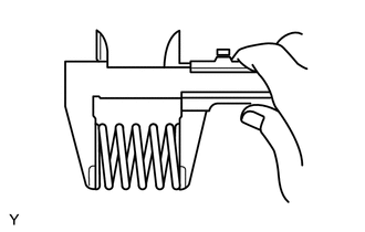
Using a vernier caliper, measure the free length of the compression spring.
Minimum length 41.5 mm (1.633 in.) If the length is not as specified, replace the compression spring.
-
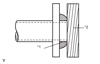
Text in Illustration *1 Gasket *2 Wooden Block Using a plastic hammer and a wooden block, tap in a new exhaust pipe gasket until its surface is flush with the exhaust manifold.
Note
-
Install the exhaust pipe gasket in the correct direction.
-
Do not damage the outer surface of the exhaust pipe gasket.
-
Do not reuse the exhaust pipe gasket.
-
Do not push in the gasket with the exhaust pipe when connecting it.
-
-
Hang the front exhaust pipe assembly with the 3 exhaust pipe supports.
-
Install the new No. 2 exhaust pipe gasket onto the front exhaust pipe assembly.
-
Install the front exhaust pipe assembly to the tail exhaust pipe assembly with the 2 bolts.
- Torque:
- 19 N*m { 194 kgf*cm, 14 ft.*lbf }
Note
Do not reuse the removed gasket.
-
Install the front exhaust pipe assembly with the 2 compression springs and 2 bolts.
- Torque:
- 43 N*m { 438 kgf*cm, 32 ft.*lbf }
-
-
INSTALL FRONT FLOOR CENTER BRACE
-
INSTALL FRONT DRIVE SHAFT ASSEMBLY RH
-
CONNECT CABLE FROM NEGATIVE BATTERY TERMINAL
-
INSPECT FOR EXHAUST GAS LEAK
-
INSPECT AND ADJUST FRONT WHEEL ALIGNMENT