EXHAUST GAS TEMPERATURE SENSOR(for Lower Side) REMOVAL
PROCEDURE
-
PRECAUTION
Note
After turning the ignition switch off, waiting time may be required before disconnecting the cable from the negative (-) battery terminal. Therefore, make sure to read the disconnecting the cable from the negative (-) battery terminal notice before proceeding with work.
-
DISCONNECT CABLE FROM NEGATIVE BATTERY TERMINAL
-
REMOVE FRONT DRIVE SHAFT ASSEMBLY RH
-
REMOVE FRONT FLOOR CENTER BRACE
-
REMOVE FRONT EXHAUST PIPE ASSEMBLY
-
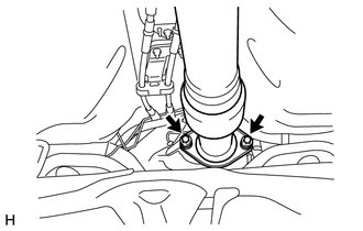
Remove the 2 bolts and 2 compression springs.
-
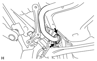
Remove the 2 bolts and separate the front exhaust pipe from the tail exhaust pipe.
-
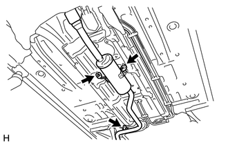
Disengage the 3 exhaust pipe supports and remove the front exhaust pipe.
-
Remove the No. 2 exhaust pipe gasket from the front exhaust pipe.
-
Remove the exhaust pipe gasket from the No. 2 exhaust manifold converter sub-assembly.
-
-
REMOVE DIFFERENTIAL PRESSURE SENSOR ASSEMBLY
-
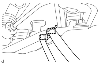
SEPARATE NO. 1 HOSE TO HOSE TUBE (for LHD)
-
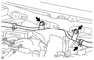
Slide the hose clip and disconnect the connector to check valve hose from the No. 1 hose to hose tube.
-
Remove the 2 bolts and separate the No. 1 hose to hose tube from the vehicle.
-
-
SEPARATE NO. 2 HOSE TO HOSE TUBE (for RHD)
-
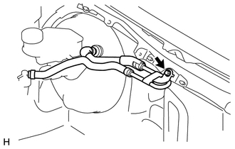
Remove the bolt and separate the No. 2 hose to hose tube from the vehicle.
-
-
REMOVE BATTERY
-
REMOVE BATTERY TRAY
-
REMOVE BATTERY CARRIER (for LHD)
-
REMOVE BATTERY CARRIER (for RHD)
-
REMOVE NO. 2 AIR HOSE
-
REMOVE NO. 1 AIR TUBE
-
REMOVE NO. 2 ENGINE COVER BRACKET
-
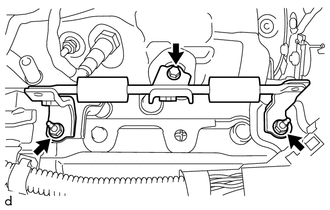
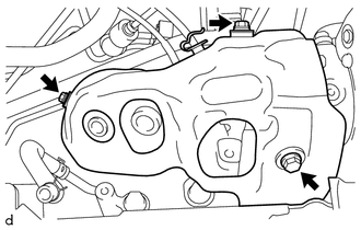
Remove the bolt, 2 nuts and No. 2 engine cover bracket from the sensor bracket and wiring harness clamp bracket.
-
-
REMOVE SENSOR BRACKET
-
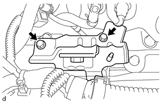
Remove the 2 bolts and sensor bracket from the cylinder head cover sub-assembly.
-
-
REMOVE AIR FUEL RATIO SENSOR (for Sensor 1)
-
REMOVE EXHAUST GAS TEMPERATURE SENSOR
-
REMOVE TURBO INSULATOR
-
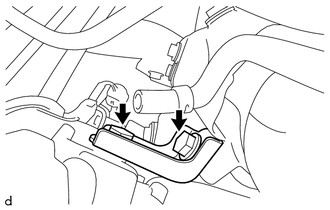
Disengage the 2 clamps to separate the air fuel ratio sensor wire and No. 2 exhaust gas temperature sensor wire from the turbo insulator.
-
Remove the 3 bolts and turbo insulator from the turbocharger sub-assembly and exhaust manifold.
-
-
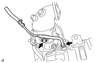
REMOVE NO. 2 PIPE
-
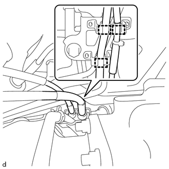
Disengage the clamp to separate the No. 2 exhaust gas temperature sensor wire from the No. 2 pipe.
-
Disengage the 2 clamps to separate the air fuel ratio sensor wire from the No. 2 pipe.
-
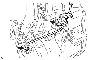
Remove the bolt to separate the No. 2 pipe from the manifold stay.
-
Using a union nut wrench 14 mm, remove the No. 2 pipe from the exhaust manifold.
-
-
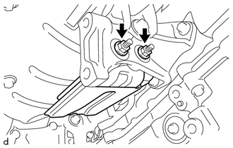
REMOVE NO. 5 CONVERTER SUPPORT BRACKET
-
Remove the 2 bolts and No. 5 converter support bracket from the exhaust manifold and cylinder block sub-assembly.
-
-
REMOVE FRONT SUSPENSION CROSSMEMBER SUB-ASSEMBLY
-
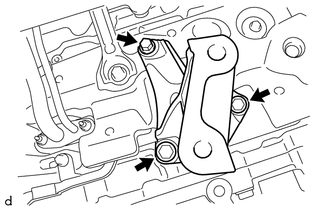
REMOVE NO. 4 CONVERTER SUPPORT BRACKET
-
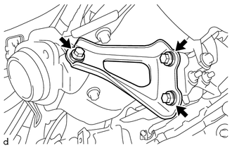
Remove the 3 bolts and No. 4 converter support bracket from the exhaust manifold and No. 1 converter support bracket.
-
-
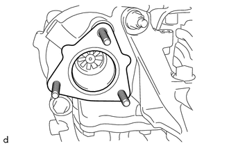
REMOVE DRIVE SHAFT HEAT INSULATOR SUB-ASSEMBLY
-
Remove the 2 nuts and drive shaft heat insulator sub-assembly from the No. 1 converter support bracket.
-
-
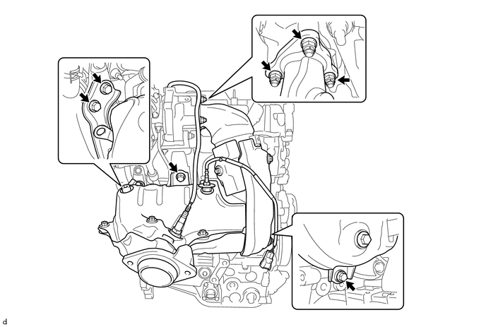
REMOVE EXHAUST MANIFOLD
-
Remove the 4 bolts, 3 nuts and exhaust manifold from the turbocharger sub-assembly, No. 1 converter support bracket, manifold stay and No. 2 converter support bracket.
-
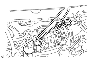
As shown in the illustration, fix the exhaust manifold to the vehicle using a rope or similar.
Note
Make sure to perform this step in order to prevent the exhaust manifold from falling.
-
Remove the 3 bolts and No. 1 converter support bracket from the cylinder block sub-assembly.
-
Remove the exhaust manifold.
-
Remove the gasket from the turbocharger sub-assembly.
-
-
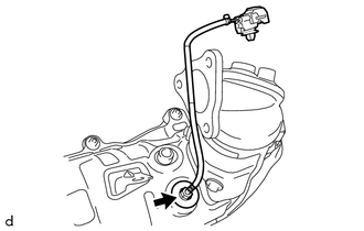
REMOVE NO. 1 PIPE
-
Remove the bolt to separate the No. 1 pipe from the exhaust manifold.
-
Using a union nut wrench 14 mm, remove the No. 1 pipe from the exhaust manifold.
-
-
REMOVE AIR FUEL RATIO SENSOR (for Sensor 2)
-
REMOVE NO. 2 EXHAUST GAS TEMPERATURE SENSOR
-
Using a union nut wrench 14 mm, remove the No. 2 exhaust gas temperature sensor from the exhaust manifold.
-