EXHAUST GAS TEMPERATURE SENSOR INSTALLATION
PROCEDURE
-
INSTALL EXHAUST GAS TEMPERATURE SENSOR
-
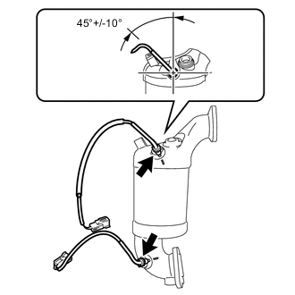
Using a union nut wrench (14 mm), install the 2 No. 2 exhaust gas temperature sensors to the exhaust manifold converter sub-assembly.
- Torque:
- 30 N*m { 306 kgf*cm, 22 ft.*lbf }
Note
-
Use the formula to calculate special torque values for situations where a union nut wrench is combined with a torque wrench Click here.
-
Do not damage the sensor.
-
Install the sensor as shown in the illustration.
-
-
INSTALL EXHAUST MANIFOLD CONVERTER SUB-ASSEMBLY
-
Install a new outlet turbine elbow gasket to the turbocharger.
-
Temporarily install the exhaust manifold converter sub-assembly with the 3 new nuts and bolt.
-
Fully tighten the 3 new nuts first, and then tighten the bolt.
- Torque:
- Nut
- 26 N*m { 265 kgf*cm, 19 ft.*lbf }
- Bolt
- 37 N*m { 377 kgf*cm, 27 ft.*lbf }
-
Install the wire harness bracket with the bolt.
- Torque:
- 9.0 N*m { 92 kgf*cm, 80 in.*lbf }
-
Install the 2 exhaust gas temperature sensors connector to the wire harness bracket.
-
Engage the 2 wire harness clamps to the wire harness bracket and cylinder block side cover.
-
Connect the 2 exhaust gas temperature sensor connectors.
-
Install the harness bracket with the bolt.
- Torque:
- 9.0 N*m { 92 kgf*cm, 80 in.*lbf }
-
Engage the 2 harness clamps to the wire harness bracket.
-
-
INSTALL NO. 1 VACUUM PIPE
-
Temporarily install the No. 1 vacuum pipe with the bolt and No. 1 vacuum pipe union nut.
-
Using a union nut wrench (14 mm), fully tighten the No. 1 vacuum pipe union nut.
- Torque:
- 48 N*m { 489 kgf*cm, 35 ft.*lbf }
Note
Use the formula to calculate special torque values for situations where a union nut wrench is combined with a torque wrench Click here.
-
Fully tighten the bolt.
- Torque:
- 21 N*m { 214 kgf*cm, 15 ft.*lbf }
-
-
INSTALL NO. 2 EXHAUST MANIFOLD CONVERTER SUB-ASSEMBLY
-
Install a new exhaust pipe gasket onto the exhaust manifold converter sub-assembly.
-
Temporarily install the No. 2 exhaust manifold converter sub-assembly with the 2 nuts.
-
Temporarily install the No. 3 manifold support bracket with the 3 bolts.
-
Temporarily install the No. 4 manifold support bracket with the 3 bolts.
-
Tighten the 2 nuts.
- Torque:
- 37 N*m { 377 kgf*cm, 27 ft.*lbf }
-
-
INSTALL NO. 3 MANIFOLD SUPPORT BRACKET
-
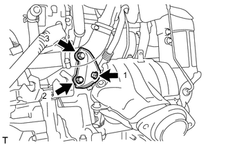
Fully tighten the 3 bolts in the order shown in the illustration.
- Torque:
- 37 N*m { 377 kgf*cm, 27 ft.*lbf }
-
-
INSTALL NO. 4 MANIFOLD SUPPORT BRACKET
-
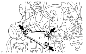
Fully tighten the 3 bolts in the order shown in the illustration.
- Torque:
- 37 N*m { 377 kgf*cm, 27 ft.*lbf }
-
-
INSTALL DRIVE SHAFT HEAT INSULATOR SUB-ASSEMBLY
-
Install the drive shaft heat insulator sub-assembly with the 2 nuts.
- Torque:
- 18 N*m { 179 kgf*cm, 13 ft.*lbf }
-
-
INSTALL NO. 2 VACUUM PIPE
-
Temporarily install the No. 2 vacuum pipe with the 2 bolts and No. 2 vacuum pipe union nut.
-
Using a union nut wrench (14 mm), fully tighten the No. 1 vacuum pipe union nut.
- Torque:
- 30 N*m { 306 kgf*cm, 22 ft.*lbf }
Note
Use the formula to calculate special torque values for situations where a union nut wrench is combined with a torque wrench Click here.
-
Fully tighten the 2 bolts.
- Torque:
- 20 N*m { 204 kgf*cm, 14 ft.*lbf }
-
-
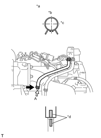
INSTALL VACUUM TRANSMITTING HOSE ASSEMBLY
-
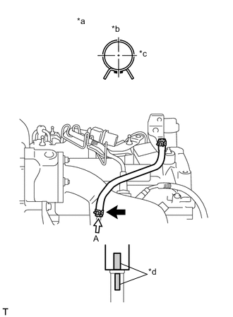
Text in Illustration *a View A *b Front of vehicle *c RH side *d Paint mark Install the vacuum transmitting hose assembly to the No. 1 vacuum pipe.
-
-
INSTALL NO. 2 VACUUM TRANSMITTING HOSE ASSEMBLY
-
Text in Illustration *a View A *b Front of vehicle *c RH side *d Paint mark Install the No. 2 vacuum transmitting hose assembly to the No. 2 vacuum pipe.
-
-
INSTALL NO. 1 TURBO INSULATOR
-
Install the No. 1 turbo insulator with the 3 bolts.
- Torque:
- 7.0 N*m { 71 kgf*cm, 62 in.*lbf }
-
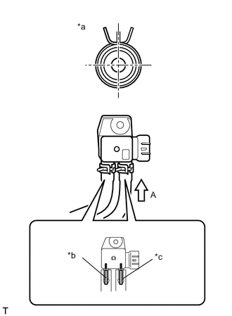
Text in Illustration *a View A *b Marked Yellow *c Marked Pink Connect the 2 vacuum transmitting hose to the differential pressure sensor.
-
-
INSTALL NO. 1 HOSE TO HOSE TUBE (for LHD)
-
Install the No. 1 hose to hose tube with the 2 bolts.
- Torque:
- 8.3 N*m { 85 kgf*cm, 73 in.*lbf }
-
Connect the connector to check valve hose to the No. 1 hose to hose tube.
-
-
INSTALL NO. 2 HOSE TO HOSE TUBE (for RHD)
-
Install the No. 2 hose to hose tube with the bolt.
- Torque:
- 8.3 N*m { 85 kgf*cm, 73 in.*lbf }
-
Connect the connector to check valve hose to the No. 2 hose to hose tube.
-
-
INSTALL NO. 2 ENGINE COVER BRACKET
-
Install the air fuel ratio sensor bracket to the cylinder head cover sub-assembly.
-
Install the No. 2 engine cover bracket with the 2 nuts.
- Torque:
- 11 N*m { 112 kgf*cm, 8 ft.*lbf }
-
Engage the engine wire harness clamp to the air fuel ratio sensor bracket.
-
Install the air fuel ratio sensor wire harness and engage the 4 wire harness clamps to the air fuel ratio sensor bracket.
-
Connect the air fuel ratio sensor connector.
-
-
INSTALL FRONT SUSPENSION CROSSMEMBER SUB-ASSEMBLY
-
INSTALL FRONT EXHAUST PIPE ASSEMBLY
-
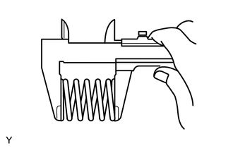
Using a vernier caliper, measure the free length of the compression spring.
Minimum length 41.5 mm (1.633 in.) If the length is not as specified, replace the compression spring.
-
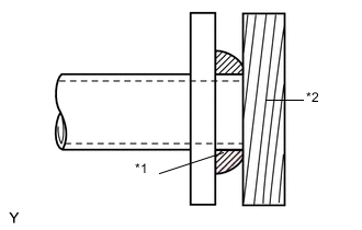
Text in Illustration *1 Gasket *2 Wooden Block Using a plastic hammer and a wooden block, tap in a new exhaust pipe gasket until its surface is flush with the exhaust manifold.
Note
-
Install the exhaust pipe gasket in the correct direction.
-
Do not damage the outer surface of the exhaust pipe gasket.
-
Do not reuse the exhaust pipe gasket.
-
Do not push in the gasket with the exhaust pipe when connecting it.
-
-
Hang the front exhaust pipe assembly with the 3 exhaust pipe supports.
-
Install the new No. 2 exhaust pipe gasket onto the front exhaust pipe assembly.
-
Install the front exhaust pipe assembly to the tail exhaust pipe assembly with the 2 bolts.
- Torque:
- 19 N*m { 194 kgf*cm, 14 ft.*lbf }
Note
Do not reuse the removed gasket.
-
Install the front exhaust pipe assembly with the 2 compression springs and 2 bolts.
- Torque:
- 43 N*m { 438 kgf*cm, 32 ft.*lbf }
-
-
INSTALL FRONT FLOOR CENTER BRACE
-
INSTALL OUTER COWL TOP PANEL (for LHD)
-
INSTALL OUTER COWL TOP PANEL (for RHD)
-
INSTALL INNER COWL TOP TO COWL BRACE (for LHD)
-
INSTALL INNER COWL TOP TO COWL BRACE (for RHD)
-
INSTALL FRONT AIR SHUTTER SEAL RH (for LHD)
-
INSTALL FRONT AIR SHUTTER SEAL RH (for RHD)
-
INSTALL FRONT NO. 1 VENTILATOR SEAL (for LHD)
-
INSTALL FRONT NO. 1 VENTILATOR SEAL (for RHD)
-
INSTALL FRONT WIPER MOTOR AND LINK
-
INSPECT FOR EXHAUST GAS LEAK
-
INSTALL NO. 1 ENGINE COVER