EXHAUST GAS TEMPERATURE SENSOR REMOVAL
PROCEDURE
-
REMOVE FRONT WIPER MOTOR AND LINK
-
REMOVE FRONT NO. 1 VENTILATOR SEAL (for LHD)
-
REMOVE FRONT NO. 1 VENTILATOR SEAL (for RHD)
-
REMOVE FRONT AIR SHUTTER SEAL RH (for LHD)
-
REMOVE FRONT AIR SHUTTER SEAL RH (for RHD)
-
REMOVE INNER COWL TOP TO COWL BRACE (for LHD)
-
REMOVE INNER COWL TOP TO COWL BRACE (for RHD)
-
REMOVE OUTER COWL TOP PANEL (for LHD)
-
REMOVE OUTER COWL TOP PANEL (for RHD)
-
REMOVE FRONT FLOOR CENTER BRACE
-
REMOVE FRONT EXHAUST PIPE ASSEMBLY
-
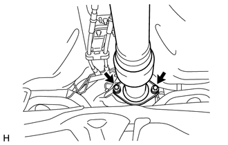
Remove the 2 bolts and 2 compression springs.
-
Remove the 2 bolts and separate the front exhaust pipe from the tail exhaust pipe.
-
Disengage the 3 exhaust pipe supports and remove the front exhaust pipe.
-
Remove the No. 2 exhaust pipe gasket from the front exhaust pipe.
-
Remove the exhaust pipe gasket from the No. 2 exhaust manifold converter sub-assembly.
-
-
REMOVE FRONT SUSPENSION CROSSMEMBER SUB-ASSEMBLY
-
REMOVE NO. 1 ENGINE COVER
-
REMOVE NO. 2 ENGINE COVER BRACKET
-
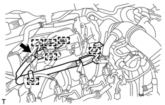
Disconnect the air fuel ratio sensor connector.
-
Disengage the 4 wire harness clamps and separate the air fuel ratio sensor wire harness.
-
Disengage the 2 engine wire harness clamps.
-
Remove the 2 nuts and No. 2 engine cover bracket.
-
Remove the air fuel ratio sensor bracket and the harness bracket.
-
-
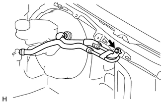
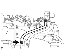
SEPARATE NO. 1 HOSE TO HOSE TUBE (for LHD)
-
Disconnect the connector to check valve hose from the No. 1 hose to hose tube.
-
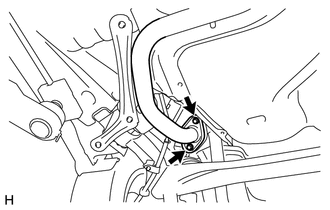
Remove the 2 bolts and separate the No. 1 hose to hose tube.
-
-
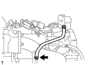
SEPARATE NO. 2 HOSE TO HOSE TUBE (for RHD)
-
Remove the bolt and separate the No. 2 hose to hose tube.
-
-
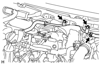
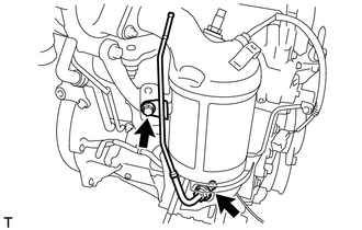
REMOVE NO. 1 TURBO INSULATOR
-
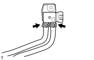
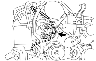
Disconnect the 2 vacuum transmitting hoses and remove the differential pressure sensor assembly.
-
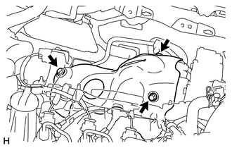
Remove the 3 bolts and No. 1 turbo insulator.
-
-
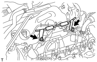
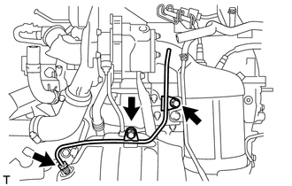
REMOVE NO. 2 VACUUM TRANSMITTING HOSE ASSEMBLY
-
Remove the No. 2 vacuum transmitting hose assembly from the No. 2 vacuum pipe.
-
-
REMOVE VACUUM TRANSMITTING HOSE ASSEMBLY
-
Remove the vacuum transmitting hose assembly from the No. 1 vacuum pipe.
-
-
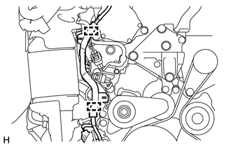
REMOVE NO. 2 VACUUM PIPE
-
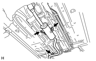
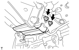
Remove the 2 bolts.
-
Using a union nut wrench (14 mm), remove the No. 2 vacuum pipe.
-
-
REMOVE DRIVE SHAFT HEAT INSULATOR SUB-ASSEMBLY
-
Remove the 2 nuts and drive shaft heat insulator sub-assembly from the No. 4 manifold support bracket.
-
-
REMOVE NO. 4 MANIFOLD SUPPORT BRACKET
-
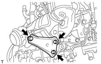
Remove the 3 bolts and No. 4 manifold support bracket from the No. 1 manifold support bracket and No. 2 exhaust manifold converter sub-assembly.
-
-
REMOVE NO. 3 MANIFOLD SUPPORT BRACKET
-
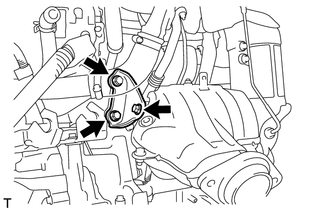
Remove the 3 bolts and No. 3 manifold support bracket from the cylinder block and No. 2 exhaust manifold converter sub-assembly.
-
-
REMOVE NO. 2 EXHAUST MANIFOLD CONVERTER SUB-ASSEMBLY
-
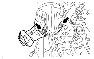
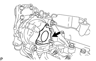
Remove the 2 nuts and No. 2 exhaust manifold converter sub-assembly from the exhaust manifold converter sub-assembly.
-
Remove the exhaust pipe gasket from the exhaust manifold converter sub-assembly.
-
-
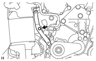
REMOVE NO. 1 VACUUM PIPE
-
Remove the bolt.
-
Using a union nut wrench (14 mm), remove the No. 1 vacuum pipe from the exhaust manifold converter sub-assembly.
-
-
REMOVE EXHAUST MANIFOLD CONVERTER SUB-ASSEMBLY
-
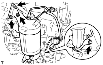
Disengage the 2 harness clamps from the harness bracket.
-
Remove the bolt and harness bracket.
-
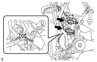
Disconnect the 2 exhaust gas temperature sensor connectors.
-
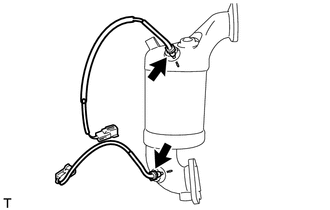
Disengage the 2 wire harness clamps from the wire harness bracket and cylinder block side cover.
-
Separate the 2 exhaust temperature sensor connectors from the wire harness bracket.
-
Remove the bolt and the wire harness bracket.
-
Remove the bolt, 3 nuts and the exhaust manifold converter sub-assembly.
-
Remove the outlet turbine elbow gasket from the turbocharger.
-
-
REMOVE EXHAUST GAS TEMPERATURE SENSOR
-
Using a union nut wrench (14 mm), remove the 2 exhaust gas temperature sensors.
-