CAUTION / NOTICE / HINT
After turning the ignition switch off, waiting time may be required before disconnecting the cable from the battery terminal. Therefore, make sure to read the disconnecting the cable from the battery terminal notice before proceeding with work. (Click here)
PROCEDURE
- Click here
REMOVE DECK BOARD ASSEMBLY
- Click here
REMOVE SPARE WHEEL COVER
- Click here
REMOVE REAR SEAT ASSEMBLY LH
- Click here
REMOVE REAR SEAT ASSEMBLY RH
- Click here
REMOVE REAR SEATBACK CENTER HINGE SUB-ASSEMBLY
- Click here
DISCHARGE FUEL SYSTEM PRESSURE
- Click here
DISCONNECT CABLE FROM NEGATIVE BATTERY TERMINAL
- Click here
DISCONNECT FUEL TANK MAIN TUBE SUB-ASSEMBLY
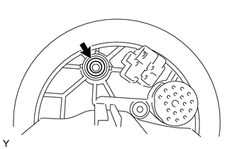
-
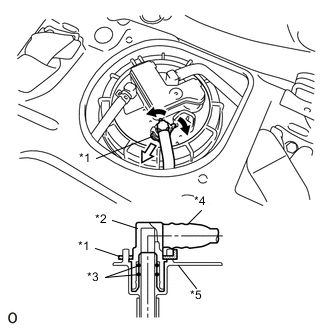
Spread the tip of the tube joint clip, and pull it out in the direction of the arrow.
Table 1. Text in Illustration *1 Tube Joint Clip *2 Fuel Tube Joint *3 O-Ring *4 Nylon Tube *5 Fuel Suction Plate 
Widen 
Pull Out -
Disconnect the fuel main tube from the fuel tank assembly.
Note:
-
Clean off any dirt or other foreign matter from the clip before beginning work.
-
The fuel tube joint is sealed by O-rings to the fuel pump tube and the fuel suction plate, so be careful to prevent damage to and foreign matter sticking to the contact surfaces.
-
Perform installation and removal procedures with your hands only. Never use any tools.
-
Do not forcibly bend, fold, or twist the nylon tube.
-
After disconnecting, protect the contact surfaces by covering them with a plastic bag.
-
If the nylon tube and fuel suction plate are stuck together, push them together and pull them apart to release them.
-
-
- Click here
SEPARATE NO. 2 FUEL EMISSION TUBE
-
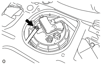
Remove the clip and disconnect the No. 2 fuel emission tube from the fuel suction plate.
-
- Click here
SEPARATE NO. 1 CANISTER OUTLET HOSE SUB-ASSEMBLY
-
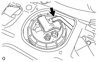
Disconnect the No. 1 canister outlet hose sub-assembly from the fuel suction plate.
-
- Click here
REMOVE FUEL PUMP GAUGE RETAINER
Note:Before performing the work, cover the connector of the fuel suction tube assembly and the tube joint with a plastic bag to prevent foreign matter from entering, and then clean off any dirt or other foreign matter.
-
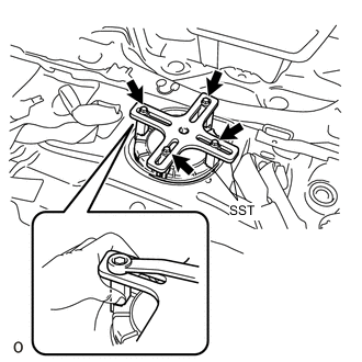
Install SST to the fuel pump gauge retainer.
09808-14030 09808-01010 09808-01020 09808-01030 09808-01040 09808-01050
-
Temporarily install plate and claw to the fuel pump gauge retainer.
-
Press claw against the rib of the fuel pump gauge retainer, and tighten bolt.
-
Install SST handle.
-
-
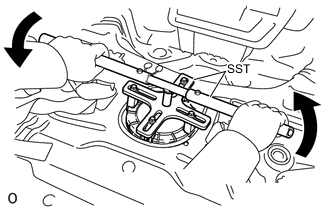
While making sure that SST does not rise up, slowly turn handle and loosen the fuel pump gauge retainer.
Note:
-
Be careful not to apply excessive downward force to SST, as this may damage the fuel pump or fuel tank.
-
Turning SST at an angle may cause it to slip off of the fuel pump gauge retainer, so be sure SST is horizontal when turning.
-
To prevent damage to parts, do not turn SST too vigorously.
-
If SST slips off of the fuel pump gauge retainer, loosen SST (bolt) and install SST again.
-
-
While holding down the fuel suction tube assembly, remove the fuel tank pump gauge retainer.
-
- Click here
REMOVE FUEL SUCTION TUBE ASSEMBLY WITH PUMP AND GAUGE
-
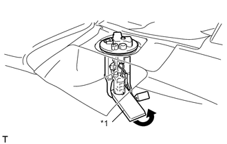
After bending up the tip of the fuel pump filter and pulling it out, pull out the arm of the fuel sender gauge assembly, and remove the fuel suction tube assembly from the fuel tank.
Table 2. Text in Illustration *1 Fuel Pump Filter Direction to Bend Note:
-
Be careful not to bend the arm of the fuel sender gauge assembly.
-
When installing or removing the fuel suction tube assembly, be careful of fuel splashing.
-
Do not damage the fuel pump filter.
-
When setting down the fuel suction tube assembly, make sure that its weight is not pressing on the fuel pump filter.
-
-
- Click here
REMOVE FUEL SUCTION TUBE SET GASKET
-
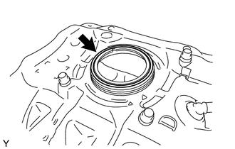
Remove the fuel suction tube set gasket.
-
- Click here
DRAIN FUEL
- Click here
REMOVE FUEL SENDER GAUGE ASSEMBLY
- Click here
REMOVE FUEL PUMP HARNESS
- Click here
REMOVE FUEL PUMP FILTER
- Click here
REMOVE FUEL PUMP
- Click here
REMOVE NO. 2 FUEL SUCTION SUPPORT
- Click here
REMOVE FUEL PRESSURE REGULATOR ASSEMBLY
- Click here
REMOVE CHARCOAL CANISTER SUB-ASSEMBLY
-
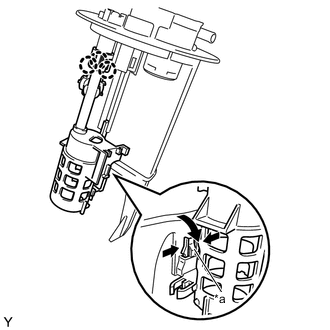
Disengage the 3 claws as shown in the illustration.
Table 3. Text in Illustration *a Lock -
Release the lock, disengage the 2 claws, then slide the No. 1 fuel suction support and remove it from the charcoal canister sub-assembly.
-
Remove the O-ring from the charcoal canister sub-assembly.
-