FUEL INJECTOR INSPECTION

PROCEDURE
-
INSPECT FUEL INJECTOR ASSEMBLY
-
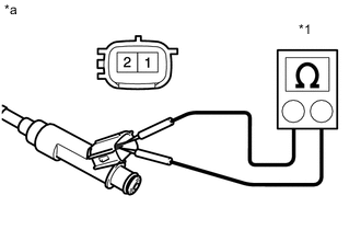
Text in Illustration *1 Ohmmeter *a Component without harness connected
(Fuel Injector Assembly)
Check the resistance.
-
Measure the resistance according to the value(s) in the table below.
Standard Resistance Tester Connection Condition Specified Condition 1 - 2 20°C (68°F) 11.6 to 12.4 Ω If the result is not as specified, replace the injector assembly.
Tech Tips
After replacing the fuel injector assembly, perform the "Inspection After Repairs" Click here.
-
-
Check the operation.
CAUTION:
Perform the inspection in a well-ventilated area.
Do not perform the inspection near any open flames.
-
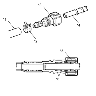
Text in Illustration *1 SST (Hose) *2 SST (Clip) *3 SST (Fuel Tube Connector) *4 Fuel Pipe *5 Retainer *6 O-ring Connect SST (fuel tube connector) to SST (hose), and then connect them to the fuel pipe (vehicle side).
- SST
- 09268-31013 ( 90467-13001, 95336-08070, 09268-41500 )
-
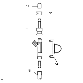
Text in Illustration *1 SST (Hose) *2 SST (Clip) *3 SST (Adapter) *4 SST (Clamp) *5 Vinyl Tube Install the new O-ring onto the fuel injector.
-
Connect SST (adapter and hose) to the injector, and hold the injector and union with SST (clamp).
- SST
- 09268-31013 ( 09268-41141, 09268-41410, 90467-13001, 95336-08070 )
-
Put the injector into a graduated cylinder.
CAUTION:
Install a suitable vinyl tube onto the injector assembly to prevent gasoline splashes.
-
Operate the fuel pump Click here.
-
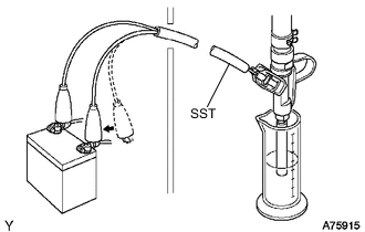
Connect SST (wire) to the injector assembly and the battery for 15 seconds, and measure the injection volume with the graduated cylinder. Test each injector 2 or 3 times.
Text in Illustration 
Connect - SST
- 09842-30080
Injection Volume Tester Connection Condition Specified Condition Positive terminal - Ground terminal Per 15 seconds 47 to 58 cm3(2.9 to 3.5 cu in.)
Difference between each injector 12 cm3 (0.7 cu in.) or less CAUTION:
Always do the switching at the battery side.
If the injection volume is not as specified, replace the injector assembly.
Tech Tips
After replacing the fuel injector assembly, perform the "Inspection After Repairs" Click here.
-
-
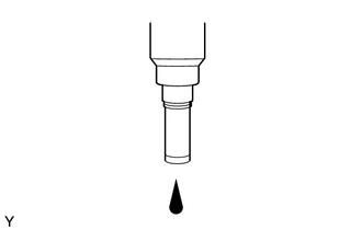
Check for leaks.
-
In the condition above, disconnect the test probes of SST (wire) from the battery and check if the fuel leaks from the injector.
Fuel Drop 1 drop or less every 12 minutes
-
-