FUEL INJECTOR INSTALLATION

CAUTION / NOTICE / HINT
PROCEDURE
-
INSTALL FUEL INJECTOR ASSEMBLY
-
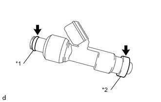
*1 O-ring *2 Injector Vibration Insulator Apply a light coat of gasoline or spindle oil to new injector vibration insulators and new O-rings, and then install one to each fuel injector assembly.
-
Apply a light coat of gasoline or spindle oil where the fuel delivery pipe contacts each O-ring.
-
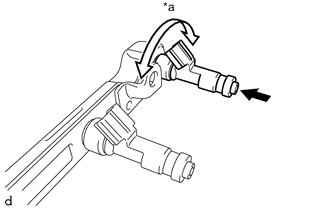
*a Turn 
Push While turning the fuel injector assembly left and right, install it to the fuel delivery pipe.
Note
-
Do not damage the fuel injector assembly or O-ring.
-
Make sure that the O-ring is not twisted or moved out of place when installing the fuel injector assembly.
-
After installing each fuel injector assembly, check that it turns smoothly. If not, replace the O-ring with a new one.
Tech Tips
Use the same procedure to install the other fuel injector assemblies.
-
-
-
INSTALL NO. 1 DELIVERY PIPE SPACER
-
Install the 2 No. 1 delivery pipe spacers to the cylinder head sub-assembly.
-
-
INSTALL FUEL DELIVERY PIPE
-
Install the fuel delivery pipe with the 4 fuel injector assemblies.
Note
Do not drop the fuel injector assemblies when installing the fuel delivery pipe.
-
Install the 2 washers.
-
Install the plate.
-
Install the 2 bolts.
- Torque:
- 21 N*m { 214 kgf*cm, 15 ft.*lbf }
-
Install the bolt.
- Torque:
- 21 N*m { 214 kgf*cm, 15 ft.*lbf }
Note
After installing the fuel delivery pipe, check that the fuel injector assemblies turn smoothly.
-
-
CONNECT FUEL TUBE SUB-ASSEMBLY
Note
Check that there is no damage or foreign matter on the connecting parts of the fuel lines.
-
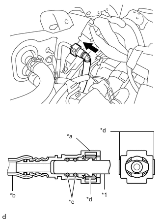
*1 Fuel Pipe *a Fuel Tube Connector *b Nylon Tube *c O-ring *d Retainer Push Connect the fuel tube sub-assembly to the fuel pipe.
-
Align the fuel tube connector with the fuel pipe, and push them together until the fuel tube connector makes a "click" sound. If it is difficult to push the fuel pipe into the fuel tube connector, apply a small amount of clean gasoline to the tip of the fuel pipe and reinsert it.
-
After connecting the fuel lines, check that the fuel pipe and fuel tube connector are securely connected by pulling on them.
-
-
-
INSTALL NO. 1 FUEL PIPE CLAMP
-
Engage the 2 claws and install the No. 1 fuel pipe clamp to the fuel tube sub-assembly and fuel pipe.
Tech Tips
The half connection prevention connector prevents the fuel hose connector cover from being locked if the fuel tube is not securely connected.
-
-
CONNECT FUEL VAPOR FEED HOSE
-
Connect the fuel vapor feed hose to the air tube.
-
-
CONNECT NO. 1 VACUUM TRANSMITTING HOSE
-
Connect the No. 1 vacuum transmitting hose to the air tube and slide the hose clip to secure it.
-
-
CONNECT ENGINE WIRE
-
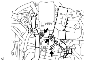
Engage the 2 clamps.
-
Install the 2 nuts.
- Torque:
- 10 N*m { 102 kgf*cm, 7 ft.*lbf }
-
Connect the connector.
-
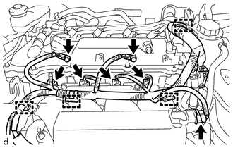
Connect the 5 connectors.
-
Engage the 4 clamps.
-
Install the 2 bolts to connect the engine wire.
- Torque:
- 10 N*m { 102 kgf*cm, 7 ft.*lbf }
-
-
CONNECT RESERVE TANK OUTLET HOSE
-
Connect the reserve tank outlet hose to the intercooler reserve tank assembly and slide the hose clip to secure it.
-
-
CONNECT NO. 3 RADIATOR HOSE
-
INSTALL BATTERY CARRIER
-
INSTALL BATTERY TRAY
-
INSTALL BATTERY
-
INSTALL AIR CLEANER CASE SUB-ASSEMBLY
-
INSTALL AIR CLEANER FILTER ELEMENT SUB-ASSEMBLY
-
INSTALL AIR CLEANER CAP WITH AIR CLEANER HOSE
-
CONNECT NO. 2 VENTILATION HOSE
-
ADD ENGINE COOLANT
-
ADD COOLANT (for Intercooler)
-
INSPECT FOR COOLANT LEAK
-
INSPECT FOR COOLANT LEAK (for Intercooler)
-
INSPECT FOR FUEL LEAK