COMMON RAIL(w/ DPF) INSTALLATION
PROCEDURE
-
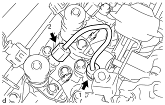
INSTALL COMMON RAIL ASSEMBLY
-
Engage the clamp to install the hose clamp to the common rail assembly.
-
Engage the clamp, and while connecting the No. 4 water by-pass hose, install the common rail assembly to the cylinder head sub-assembly.
-
Install the 2 bolts.
- Torque:
- 21 N*m { 214 kgf*cm, 15 ft.*lbf }
-
Connect the No. 2 fuel hose to the common rail assembly and slide the hose clip to secure it.
-
Connect the pressure control valve connector.
-
Connect the rail pressure sensor connector.
-
-
INSTALL NO. 4 INJECTION PIPE SUB-ASSEMBLY
-
To prevent contamination by foreign matter, do not remove the plastic bag that was protecting the connector portion of the injector assembly and common rail assembly until immediately before installing the No. 4 injection pipe sub-assembly.
-
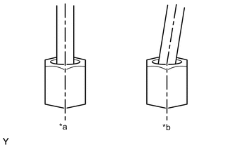
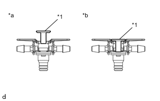
Text in Illustration *a Correct *b Incorrect Temporarily install new No. 4 injection pipe sub-assembly to the injector assembly and common rail assembly.
Note
-
When installing, the sealing surface of the No. 4 injection pipe sub-assembly should be fitted tightly against the injector assembly and common rail assembly.
-
When installing, do not tilt or angle the sealing surface of the No. 4 injection pipe sub-assembly.
-
When installing, tighten the union nut of the No. 4 injection pipe sub-assembly by hand until it cannot be turned any further.
-
-
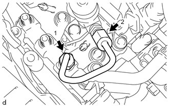
Using a union nut wrench 17 mm, fully tighten the 2 union nuts in the order shown in the illustration.
- Torque:
- Specified tightening torque
- 28 N*m { 286 kgf*cm, 21 ft.*lbf }
Note
When fully tightening the union nuts, make sure to tighten from the common rail assembly.
Tech Tips
-
Calculate the torque wrench reading when changing the fulcrum length of the torque wrench.
-
When a union nut wrench 17 mm (fulcrum length of 30 mm (1.18 in.)) + torque wrench (fulcrum length of 260 mm (10.2 in.)): 24N*m (245 kgf*cm, 18 ft.*lbf)
-
-
INSTALL FUEL INLET PIPE SUB-ASSEMBLY
-
To prevent contamination by foreign matter, do not remove the plastic bag that was protecting the connector portion of the injector assembly and common rail assembly until immediately before installing the fuel inlet pipe sub-assembly.
-
Text in Illustration *a Correct *b Incorrect Temporarily install new fuel inlet pipe sub-assembly to the injection or supply pump assembly and common rail assembly.
Note
-
When installing, the sealing surface of the fuel inlet pipe sub-assembly should be fitted tightly against the injector assembly and common rail assembly.
-
When installing, do not tilt or angle the sealing surface of the fuel inlet pipe sub-assembly.
-
When installing, tighten the union nut of the fuel inlet pipe sub-assembly by hand until it cannot be turned any further.
-
-
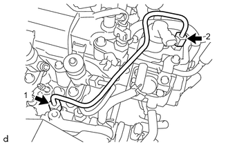
Using a union nut wrench 17 mm, fully tighten the 2 union nuts in the order shown in the illustration.
- Torque:
- Specified tightening torque
- 28 N*m { 286 kgf*cm, 21 ft.*lbf }
Note
When fully tightening the union nuts, make sure to tighten from the common rail assembly.
Tech Tips
-
Calculate the torque wrench reading when changing the fulcrum length of the torque wrench.
-
When a union nut wrench 17 mm (fulcrum length of 30 mm (1.18 in.)) + torque wrench (fulcrum length of 260 mm (10.2 in.)): 24N*m (245 kgf*cm, 18 ft.*lbf)
-
Install the No. 2 injection pipe clamp to the fuel inlet pipe sub-assembly and No. 4 injection pipe sub-assembly with the bolt.
- Torque:
- 5.0 N*m { 51 kgf*cm, 44 in.*lbf }
-
Install the No. 3 engine cover bracket to the EGR cooler bracket with the bolt.
- Torque:
- 9.0 N*m { 92 kgf*cm, 80 in.*lbf }
-
-
INSTALL NO. 3 INJECTION PIPE SUB-ASSEMBLY
-
To prevent contamination by foreign matter, do not remove the plastic bag that was protecting the connector portion of the injector assembly and common rail assembly until immediately before installing the No. 3 injection pipe sub-assembly.
-
Text in Illustration *a Correct *b Incorrect Temporarily install new No. 3 injection pipe sub-assembly to the injector assembly and common rail assembly.
Note
-
When installing, the sealing surface of the No. 3 injection pipe sub-assembly should be fitted tightly against the injector assembly and common rail assembly.
-
When installing, do not tilt or angle the sealing surface of the No. 3 injection pipe sub-assembly.
-
When installing, tighten the union nut of the No. 3 injection pipe sub-assembly by hand until it cannot be turned any further.
-
-
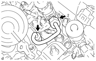
Using a union nut wrench 17 mm, fully tighten the 2 union nuts in the order shown in the illustration.
- Torque:
- Specified tightening torque
- 28 N*m { 286 kgf*cm, 21 ft.*lbf }
Note
When fully tightening the union nuts, make sure to tighten from the common rail assembly.
Tech Tips
-
Calculate the torque wrench reading when changing the fulcrum length of the torque wrench.
-
When a union nut wrench 17 mm (fulcrum length of 30 mm (1.18 in.)) + torque wrench (fulcrum length of 260 mm (10.2 in.)): 24N*m (245 kgf*cm, 18 ft.*lbf)
-
Connect the vacuum transmitting pipe sub-assembly to the EGR cooler bracket with the bolt.
- Torque:
- 9.0 N*m { 92 kgf*cm, 80 in.*lbf }
-
Connect the vacuum hose to the No. 2 EGR valve assembly.
-
-
INSTALL NO. 2 INJECTION PIPE SUB-ASSEMBLY
-
To prevent contamination by foreign matter, do not remove the plastic bag that was protecting the connector portion of the injector assembly and common rail assembly until immediately before installing the No. 2 injection pipe sub-assembly.
-
Text in Illustration *a Correct *b Incorrect Temporarily install new No. 2 injection pipe sub-assembly to the injector assembly and common rail assembly.
Note
-
When installing, the sealing surface of the No. 2 injection pipe sub-assembly should be fitted tightly against the injector assembly and common rail assembly.
-
When installing, do not tilt or angle the sealing surface of the No. 2 injection pipe sub-assembly.
-
When installing, tighten the union nut of the No. 2 injection pipe sub-assembly by hand until it cannot be turned any further.
-
-
Using a union nut wrench 17 mm, fully tighten the 2 union nuts in the order shown in the illustration.
- Torque:
- Specified tightening torque
- 28 N*m { 286 kgf*cm, 21 ft.*lbf }
Note
When fully tightening the union nuts, make sure to tighten from the common rail assembly.
Tech Tips
-
Calculate the torque wrench reading when changing the fulcrum length of the torque wrench.
-
When a union nut wrench 17 mm (fulcrum length of 30 mm (1.18 in.)) + torque wrench (fulcrum length of 260 mm (10.2 in.)): 24N*m (245 kgf*cm, 18 ft.*lbf)
-
-
INSTALL NO. 1 INJECTION PIPE SUB-ASSEMBLY
-
To prevent contamination by foreign matter, do not remove the plastic bag that was protecting the connector portion of the injector assembly and common rail assembly until immediately before installing the No. 1 injection pipe sub-assembly.
-
Text in Illustration *a Correct *b Incorrect Temporarily install new No. 1 injection pipe sub-assembly to the injector assembly and common rail assembly.
Note
-
When installing, the sealing surface of the No. 1 injection pipe sub-assembly should be fitted tightly against the injector assembly and common rail assembly.
-
When installing, do not tilt or angle the sealing surface of the No. 1 injection pipe sub-assembly.
-
When installing, tighten the union nut of the No. 1 injection pipe sub-assembly by hand until it cannot be turned any further.
-
-
Using a union nut wrench 17 mm, fully tighten the 2 union nuts in the order shown in the illustration.
- Torque:
- Specified tightening torque
- 28 N*m { 286 kgf*cm, 21 ft.*lbf }
Note
When fully tightening the union nuts, make sure to tighten from the common rail assembly.
Tech Tips
-
Calculate the torque wrench reading when changing the fulcrum length of the torque wrench.
-
When a union nut wrench 17 mm (fulcrum length of 30 mm (1.18 in.)) + torque wrench (fulcrum length of 260 mm (10.2 in.)): 24N*m (245 kgf*cm, 18 ft.*lbf)
-
-
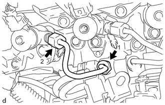
INSTALL NOZZLE LEAKAGE PIPE ASSEMBLY
Note
Perform installation and removal procedures by hand only. Do not use any tools.
-
Text in Illustration *1 Lock Bush *a Correct *b Incorrect Check that the lock bush of the nozzle leakage pipe assembly is at the highest position.
-
Insert the rest arm into the upper surface of the injector assembly, and while pressing the return plug from both sides, insert the nozzle leakage pipe assembly into each injector assembly.
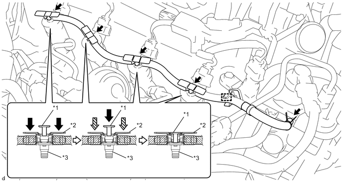
Text in Illustration *1 Lock Bush *2 Return Plug *3 Rest Arm - - 
Push 
Hold -
While holding down the return plug, push the lock bush until it meets the top position of the return plug, and secure the nozzle leakage pipe assembly in place.
-
Engage the clamp to connect the nozzle leakage pipe assembly to the hose clamp.
-
Connect the nozzle leakage pipe assembly to the No. 2 nozzle leakage pipe and slide the hose clip to secure it.
-
-
INSTALL NO. 1 VACUUM SWITCHING VALVE ASSEMBLY
-
INSTALL NO. 1 GLOW PLUG CONNECTOR
-
INSTALL NO. 1 AIR CLEANER HOSE
-
INITIALIZATION AND REGISTRATION
-
BLEED AIR FROM FUEL SYSTEM
-
INSPECT FOR FUEL LEAK
-
INSTALL NO. 1 ENGINE COVER