FUEL SUPPLY PUMP(w/ DPF) INSTALLATION
PROCEDURE
-
INSTALL NO. 3 NOZZLE LEAKAGE PIPE
-
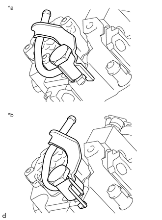
Text in Illustration *a Correct *b Incorrect Install a new gasket and No. 3 nozzle leakage pipe to the injection or supply pump assembly with the union bolt.
- Torque:
- 25 N*m { 255 kgf*cm, 18 ft.*lbf }
Note
-
When installing, make sure the detent portion of the No. 3 nozzle leakage pipe is in the location shown in the illustration.
-
Make sure the linking portion of the gasket is towards the bottom of the vehicle.
-
-
INSTALL NO. 4 NOZZLE LEAKAGE PIPE
-
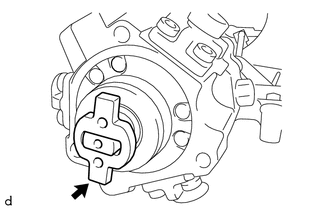
Install a new gasket and No. 4 nozzle leakage pipe to the injection or supply pump assembly with the union bolt.
- Torque:
- 20 N*m { 205 kgf*cm, 15 ft.*lbf }
Note
Make sure the linking portion of the gasket is towards the bottom of the vehicle.
-
-
INSTALL INJECTION OR SUPPLY PUMP ASSEMBLY
Note
If the supply pump drive coupling remained on the camshaft during removal, install the supply pump drive coupling to the injection or supply pump assembly.
-
Apply a light coat of engine oil to the O-ring.
Note
If reusing the injection or supply pump assembly, be sure to inspect the O-ring.
-
Install the injection or supply pump assembly to the cylinder head sub-assembly with the 3 bolts.
- Torque:
- 21 N*m { 214 kgf*cm, 15 ft.*lbf }
-
-
INSTALL FUEL PUMP PROTECTOR
-
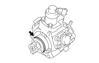
Install the fuel pump protector to the injection or supply pump assembly with the 2 bolts.
- Torque:
- 10 N*m { 105 kgf*cm, 8 ft.*lbf }
-
-
INSTALL NO. 2 NOZZLE LEAKAGE PIPE
-
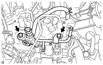
Install the No. 2 nozzle leakage pipe to the cylinder head cover sub-assembly and injection or supply pump assemblywith the 2 bolts.
- Torque:
- Bolt A
- 21 N*m { 214 kgf*cm, 15 ft.*lbf }
- Bolt B
- 9.0 N*m { 92 kgf*cm, 80 in.*lbf }
-
Connect the fuel temperature sensor connector.
-
Connect the No. 2 fuel hose to the No. 2 nozzle leakage pipe and slide the hose clip to secure it.
-
Install the wiring harness clamp bracket to the injection or supply pump assembly with the bolt.
- Torque:
- 8.4 N*m { 86 kgf*cm, 74 in.*lbf }
-
Engage the clamp to connect the wire harness to the wiring harness clamp bracket.
-
Connect the injection or supply pump assembly connector.
-
Connect the No. 1 fuel hose to the No. 4 nozzle leakage pipe and slide the hose clip to secure it.
-
-
CONNECT NO. 1 FUEL HOSE SUB-ASSEMBLY
-
Connect the No. 1 fuel hose sub-assembly to the No. 2 nozzle leakage pipe and No. 3 nozzle leakage pipe and slide the 2 hose clips to secure it.
-
-
INSTALL FUEL INLET PIPE SUB-ASSEMBLY
-
INSTALL NO. 3 INJECTION PIPE SUB-ASSEMBLY
-
INSTALL NO. 2 INJECTION PIPE SUB-ASSEMBLY
-
INSTALL NO. 1 INJECTION PIPE SUB-ASSEMBLY
-
INSTALL NOZZLE LEAKAGE PIPE ASSEMBLY
-
INSTALL NO. 1 VACUUM SWITCHING VALVE ASSEMBLY
-
INSTALL NO. 1 GLOW PLUG CONNECTOR
-
INSTALL NO. 1 AIR CLEANER HOSE
-
INSTALL NO. 1 ENGINE COVER
-
INSTALL BATTERY CARRIER (for LHD)
-
INSTALL BATTERY CARRIER (for RHD)
-
INSTALL BATTERY TRAY
-
INSTALL BATTERY
-
CONNECT CABLE FROM NEGATIVE BATTERY TERMINAL
-
INITIALIZATION AND REGISTRATION
-
BLEED AIR FROM FUEL SYSTEM
-
INSPECT FOR FUEL LEAK