FUEL SUPPLY PUMP INSTALLATION
PROCEDURE
-
INSTALL NO. 1 SUPPLY PUMP DRIVE COUPLING
-
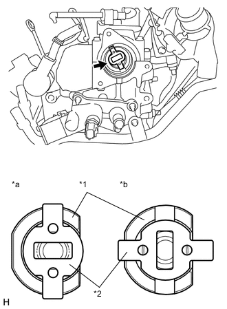
Text in Illustration *1 Camshaft *2 Supply Pump Drive Coupling *a OK *b NG Install the supply pump No. 1 drive coupling into the camshaft.
Note
Install the supply pump drive coupling in the correct direction.
-
-
INSTALL SUPPLY PUMP ASSEMBLY
Note
When installing, clean the seal surfaces of the fuel inlet pipe, supply pump and common rail.
-
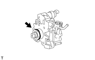
Apply a light coat of engine oil to a new O-ring.
-
Install the O-ring onto the supply pump.
-
Temporarily install the supply pump with the 3 bolts.
-
-
INSTALL FUEL INLET PIPE SUB-ASSEMBLY
Note
-
When replacing the supply pump, the fuel inlet pipe must also be replaced.
-
Replace the fuel inlet pipe with a new one when the fuel inlet pipe has been removed and reinstalled more than 5 times.
-
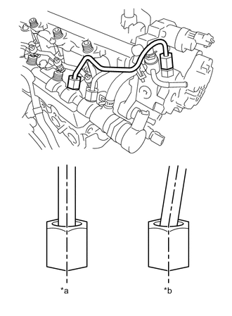
Text in Illustration *a OK *b NG Temporarily install the fuel inlet pipe onto the supply pump and common rail.
Note
Install the pipe and union nut vertically, not at a tilt.
-
Tighten the supply pump with the 3 bolts.
- Torque:
- 21 N*m { 214 kgf*cm, 15 ft.*lbf }
-
Using a union nut wrench (17 mm), tighten the fuel inlet pipe union nut on the common rail side.
- Torque:
- 28 N*m { 286 kgf*cm, 21 ft.*lbf }
Note
Use the formula to calculate special torque values for situations where a union nut wrench is combined with a torque wrench Click here.
-
Using a wrench (17 mm), hold the supply pump nut, and using a union nut wrench (17 mm), tighten the fuel inlet pipe union nut on the supply pump side.
- Torque:
- 28 N*m { 286 kgf*cm, 21 ft.*lbf }
Note
Use the formula to calculate special torque values for situations where a union nut wrench is combined with a torque wrench Click here.
-
Connect the No. 2 fuel hose.
-
Connect the nozzle leakage pipe and install a new retainer spring onto the supply pump.
-
Connect the 2 connectors.
-
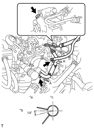
Text in Illustration *a View A *b Front Side *c Upper Side Connect the fuel pipe sub-assembly with bolt.
- Torque:
- 14 N*m { 143 kgf*cm, 11 ft.*lbf }
-
Connect the 2 fuel hoses.
-
-
INSTALL NO. 1 EGR COOLER BRACKET
-
INSTALL BATTERY
-
INSTALL AIR CLEANER CAP SUB-ASSEMBLY WITH NO. 1 AIR CLEANER HOSE
-
INSTALL EGR WITH COOLER PIPE SUB-ASSEMBLY
-
BLEED AIR FROM FUEL SYSTEM
-
INSPECT FOR FUEL LEAK