FUEL SENDER GAUGE ASSEMBLY REMOVAL

PROCEDURE
-
REMOVE DECK BOARD ASSEMBLY
-
REMOVE SPARE WHEEL COVER
-
REMOVE REAR SEAT ASSEMBLY LH
-
REMOVE REAR SEAT ASSEMBLY RH
-
REMOVE REAR SEATBACK CENTER HINGE SUB-ASSEMBLY
-
REMOVE REAR FLOOR SERVICE HOLE COVER
-
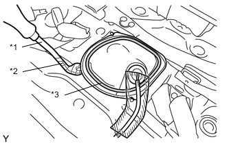
Text in Illustration *1 Clip Remover *2 Protective Tape *3 Butyl Tape Remove the rear floor service hole cover.
-
Disconnect the fuel sender gauge connector from the fuel tank vent case sub-assembly.
-
-
DISCONNECT FUEL TANK MAIN TUBE SUB-ASSEMBLY
-
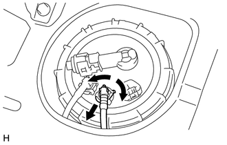
Widen the tip of the tube joint clip and pull out the clip in the direction indicated by the arrow.
-
Pull the fuel tank main tube out of the fuel tank vent tube with sender gauge assembly to disconnect it.
Note
-
Check for dirt or other foreign matter on the parts to be disconnected and clean them if necessary.
-
The fuel tube connector seals with an O-ring. Ensure that there is no damage or foreign matter on the contact surface.
-
Do not use any tools.
-
Do not bend or twist the tubes.
-
Protect the contact surface by covering it with a plastic bag.
-
If the connector is stuck, push and pull on the parts to separate them.
-
Do not damage any of the clips. If a clip is damaged, replace it.
-
-
-
DISCONNECT FUEL RETURN TUBE SUB-ASSEMBLY
-
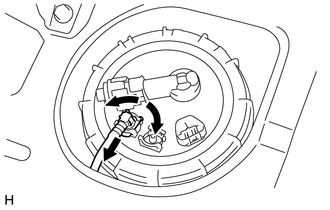
Widen the tip of the tube joint clip and pull out the clip in the direction indicated by the arrow.
-
Pull the fuel return tube out of the fuel tank vent tube with sender gauge assembly to disconnect it.
Note
-
Check for dirt or other foreign matter on the parts to be disconnected and clean them if necessary.
-
The fuel tube connector seals with an O-ring. Ensure that there is no damage or foreign matter on the contact surface.
-
Do not use any tools.
-
Do not bend or twist the tubes.
-
Protect the contact surface by covering it with a plastic bag.
-
If the connector is stuck, push and pull on the parts to separate them.
-
Do not damage any of the clips. If a clip is damaged, replace it.
-
-
-
REMOVE FUEL PUMP GAUGE RETAINER
-
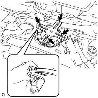
Temporarily install the SST plate and claws to the fuel pump gauge retainer.
- SST
- 09808-14030 ( 09808-01010, 09808-01020, 09808-01030, 09808-01040, 09808-01050 )
Tech Tips
Engage the SST claws securely with the fuel pump gauge retainer ribs to secure SST.
-
While pressing the claws of SST to the fuel pump gauge retainer ribs securely, tighten the bolts.
Tech Tips
Install SST while pressing the SST claws toward the fuel pump gauge retainer (towards the center of SST).
-
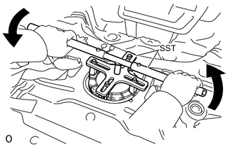
Install the SST handle.
-
Lightly press down on SST to prevent it from separating from the retainer. While pressing SST, rotate the handle slowly to loosen the retainer.
Note
-
Do not use any tools other than those specified in this operation. Damage to the fuel pump gauge retainer or fuel tank may result.
-
Do not press down on SST excessively as this may make the retainer hard to rotate, and may damage components.
-
Make sure to rotate the SST handle horizontally. If the SST handle is rotated at an angle, SST may come off.
-
Do not spin SST too fast or use an impact wrench as this may result in damage to components.
-
If SST comes off of the retainer, loosen the SST bolts and reinstall SST.
Tech Tips
The ribs on the fuel pump gauge retainer can be fitted into the tips of SST.
-
-
Remove the fuel pump gauge retainer while holding the fuel suction tube assembly by hand.
-
-
REMOVE FUEL TANK VENT TUBE ASSEMBLY WITH SENDER GAGE
-
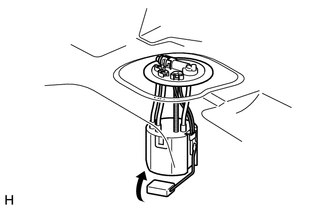
Remove the fuel tank vent tube assembly with sender gauge from the fuel tank.
Note
Make sure that the fuel sender gauge arm does not bend.
-
-
REMOVE FUEL SUCTION TUBE SET GASKET
-

Remove the fuel suction tube gasket from the fuel tank.
-
-
REMOVE FUEL SENDER GAGE ASSEMBLY
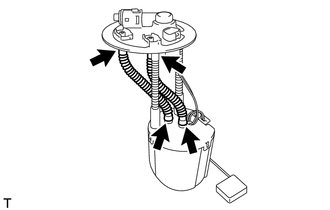
Note
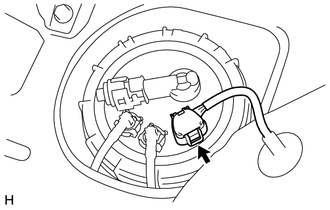
Do not disconnect the tube shown in the illustration.
-
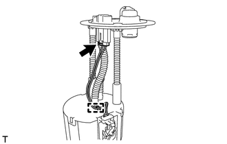
Disconnect the fuel sender gage connector and disengage the harness clamp.
-
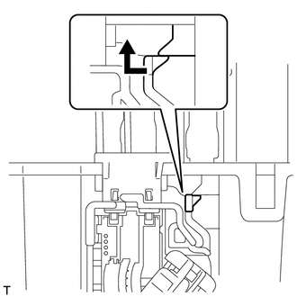
Release the lock as shown in the illustration and slide the fuel sender gage assembly to remove it.
-