ENGINE ASSEMBLY INSTALLATION

CAUTION / NOTICE / HINT
Note
When the manual transaxle is removed, be sure to use a new clutch release with bearing cylinder assembly and new installation bolts. Removal of the manual transaxle allows the compressed clutch release with bearing cylinder assembly to return to its original position, and dust could damage the seal of the clutch release with bearing cylinder assembly, possibly causing clutch fluid leaks.
PROCEDURE
-
INSTALL ENGINE MOUNTING INSULATOR LH
Tech Tips
Perform this procedure only when replacement of the engine mounting insulator LH is necessary.
-
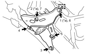
*a Temporarily Tighten Temporarily install the engine mounting insulator LH to the vehicle.
-
Install the 5 bolts in the order shown in the illustration.
- Torque:
- 52 N*m { 530 kgf*cm, 38 ft.*lbf }
-
-
INSTALL GENERATOR ASSEMBLY
-
INSTALL ENGINE HANGER
-
REMOVE ENGINE ASSEMBLY FROM ENGINE STAND
-
Using a chain block and engine sling device, secure the engine assembly.
Note
-
Adjust the angle of the sling device carefully to prevent the engine assembly or engine hangers from deforming or becoming damaged.
-
Servicing an engine assembly while it is hanging is dangerous. This can be done only when installing/removing the engine assembly to/from an engine stand.
-
-
Remove the engine assembly from the engine stand.
-
-
INSTALL FLYWHEEL SUB-ASSEMBLY
-
INSTALL CLUTCH DISC ASSEMBLY
-
INSTALL CLUTCH COVER ASSEMBLY
-
INSTALL MANUAL TRANSAXLE ASSEMBLY
-
INSTALL FLYWHEEL HOUSING SIDE COVER
-
Install the flywheel housing side cover to the cylinder block sub-assembly.
-
-
INSTALL STARTER ASSEMBLY
-
INSTALL ENGINE WIRE
-
Install the engine wire to the engine assembly with transaxle.
-
-
REMOVE ENGINE HANGER
-
Remove the bolt and engine hanger.
-
-
INSTALL WIRE HARNESS CLAMP BRACKET
-
Install the wire harness clamp bracket with the bolt.
- Torque:
- 10 N*m { 102 kgf*cm, 7 ft.*lbf }
-
Engage the 2 clamps.
-
-
INSTALL ENGINE ASSEMBLY WITH TRANSAXLE
-
Set the engine assembly with transaxle on an engine lifter.
Note
Place height adjustment attachments and plate lift attachments under the engine assembly with transaxle.
-
Operate the engine lifter and lift the engine assembly with transaxle to the position where the engine mounting insulator sub-assembly RH and engine mounting insulator LH can be installed.
CAUTION:
Do not raise the engine assembly with transaxle more than necessary. If the engine assembly with transaxle is raised excessively, the vehicle may also be lifted up.
Note
-
Make sure that the engine assembly with transaxle is clear of all wiring and hoses.
-
While raising the engine assembly with transaxle into the vehicle, do not allow it to contact the vehicle.
-
-
Install the engine mounting insulator LH with the through bolt and nut.
- Torque:
- 52 N*m { 530 kgf*cm, 38 ft.*lbf }
Tech Tips
When tightening the through bolt, keep the nut from rotating.
-
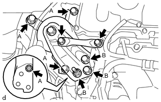
Install the engine mounting insulator sub-assembly RH with the 5 bolts and 2 nuts.
- Torque:
- Bolt, nut A
- 52 N*m { 530 kgf*cm, 38 ft.*lbf }
- Bolt, nut B
- 88 N*m { 897 kgf*cm, 65 ft.*lbf }
-
Install the engine mounting stay with the 2 bolts.
- Torque:
- 26 N*m { 265 kgf*cm, 19 ft.*lbf }
-
Temporarily install the front suspension crossmember sub-assembly to the vehicle with the 4 bolts.
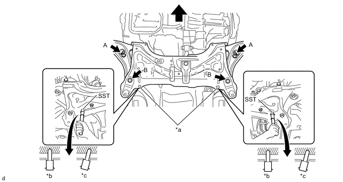
*a Datum holes *b OK *c NG - - 
Front of the Vehicle - - - SST
- 09670-00011
- Torque:
- Bolt A
- 87 N*m { 887 kgf*cm, 64 ft.*lbf }
- Bolt B
- 151 N*m { 1540 kgf*cm, 111 ft.*lbf }
-
-
INSTALL FRONT SUSPENSION MEMBER BRACE SUB-ASSEMBLY
-
CONNECT NO. 1 STEERING COLUMN HOLE COVER SUB-ASSEMBLY
-
INSTALL STEERING SLIDING YOKE SUB-ASSEMBLY
-
INSTALL COLUMN HOLE COVER SILENCER SHEET
-
INSTALL DRIVE SHAFT ASSEMBLY
-
INSTALL FRONT EXHAUST PIPE ASSEMBLY
-
INSTALL REAR CONSOLE BOX ASSEMBLY
-
INSTALL FRONT FLOOR CENTER BRACE
-
INSTALL COMPRESSOR WITH PULLEY ASSEMBLY
-
CONNECT INLET HEATER WATER HOSE
-
Connect the inlet heater water hose to the air conditioner unit assembly and slide the clip to secure it.
-
-
CONNECT OUTLET HEATER WATER HOSE
-
Connect the outlet heater water hose to air conditioner unit assembly and slide the clip to secure it.
-
-
CONNECT UNION TO CHECK VALVE HOSE
-
Connect the union to check valve hose to the air tube and slide the clip to secure it.
-
-
INSTALL NO. 1 FUEL VAPOR FEED HOSE
-
Connect the No. 1 fuel vapor feed hose to the vacuum switching valve assembly and slide the clip to secure it.
-
-
CONNECT FUEL TUBE SUB-ASSEMBLY
-
Connect the fuel tube connector and fuel pipe.
CAUTION:
Align the fuel tube connector with the fuel pipe, then push the fuel tube connector in until the retainer makes a "click" sound. If the connection is tight, apply a small amount of engine oil to the tip of the fuel pipe. After connecting, pull the fuel pipe and fuel tube connector to make sure that they are securely connected.
-
Engage the claw and install the No. 1 fuel pipe clamp.
-
-
CONNECT CLUTCH HOSE
-
CONNECT TRANSMISSION CONTROL CABLE ASSEMBLY
-
CONNECT RADIATOR HOSE
-
Connect the radiator hose to the water inlet and slide the clip to secure it.
-
-
CONNECT RESERVE TANK OUTLET HOSE
-
CONNECT RESERVE TANK INLET HOSE
-
Connect the reserve tank inlet hose to the intercooler reserve tank assembly and slide the clip to secure it.
-
-
CONNECT NO. 7 SUB-RADIATOR HOSE
-
CONNECT NO. 4 SUB-RADIATOR HOSE
-
CONNECT NO. 3 RADIATOR HOSE
-
Connect the No. 3 radiator hose to the cylinder head sub-assembly and slide the clip to secure it.
-
-
INSTALL FAN AND GENERATOR V BELT
-
INSPECT FAN AND GENERATOR V BELT
-
CONNECT WIRE HARNESS
-
Connect all the wire harnesses and connectors.
-
Install the bolt and connect the 2 wire harness clamp to the manual transaxle assembly.
- Torque:
- 12.8 N*m { 131 kgf*cm, 9 ft.*lbf }
-
Connect the 2 wire harness connectors to the positive (+) battery terminal.
-
Engage the 2 claws and wire harness to the engine room relay block and junction block assembly.
-
Connect the 2 wire harness connectors and wire harness to the engine room relay block and junction block assembly.
-
Connect the wire harness clamp.
-
Install the No. 1 engine room relay block cover to the engine room relay block and junction block assembly.
-
Connect the wire harness clamp.
-
Pull down the lever to connect the 2 ECM connectors.
-
Connect the clamp and wire harness to the air cleaner blacket.
-
-
INSTALL BATTERY CARRIER
-
Install the battery carrier with the 5 bolts.
- Torque:
- 17.2 N*m { 175 kgf*cm, 13 ft.*lbf }
-
Connect the 6 wire harness clamps to the battery carrier.
-
-
INSTALL BATTERY TRAY
-
Install the battery tray to the battery carrier.
-
-
INSTALL BATTERY
-
Install the battery.
-
Install the battery clamp bolt and battery clamp sub-assembly with the 2 nuts.
- Torque:
- 3.5 N*m { 36 kgf*cm, 31 in.*lbf }
-
Connect the cable to the positive (+) battery terminal with the nut.
- Torque:
- 5.4 N*m { 55 kgf*cm, 48 in.*lbf }
-
-
INSTALL AIR CLEANER CASE SUB-ASSEMBLY
-
Install the air cleaner case sub-assembly with the 2 bolts.
- Torque:
- 7.8 N*m { 80 kgf*cm, 69 in.*lbf }
-
Connect the wire harness clamp to the air cleaner case sub-assembly.
-
-
INSTALL AIR CLEANER FILTER ELEMENT SUB-ASSEMBLY
-
Install the air cleaner filter element sub-assembly to air cleaner case sub-assembly.
-
-
INSTALL AIR CLEANER CAP WITH AIR CLEANER HOSE
-
INSTALL FRONT SUSPENSION UPPER CENTER BRACE SUB-ASSEMBLY
-
Install the front suspension upper center brace sub-assembly to the front suspension upper to cowl brace bracket LH and front suspension upper to cowl brace bracket RH with the 4 nuts.
- Torque:
- 50 N*m { 510 kgf*cm, 37 ft.*lbf }
-
-
INSTALL OUTER COWL TOP PANEL
-
for TMMF made LHD:
-
for TMMF made RHD:
-
-
INSTALL INNER COWL TOP TO COWL BRACE
-
for TMMF made LHD:
-
for TMMF made RHD:
-
-
INSTALL FRONT AIR SHUTTER SEAL RH
-
for TMMF made LHD:
-
for TMMF made RHD:
-
-
INSTALL FRONT NO. 1 VENTILATOR SEAL
-
for TMMF made LHD:
-
for TMMF made RHD:
-
-
INSTALL WINDSHIELD WIPER LINK ASSEMBLY
-
CONNECT CABLE TO NEGATIVE BATTERY TERMINAL
-
Connect the cable to the negative (-) battery terminal.
- Torque:
- 5.4 N*m { 55 kgf*cm, 48 in.*lbf }
Note
When disconnecting the cable, some systems need to be initialized after the cable is reconnected.
-
-
ADD MANUAL TRANSAXLE OIL
-
ADJUST TRANSMISSION CONTROL SELECT CABLE
-
ADD ENGINE COOLANT
-
ADD ENGINE COOLANT (for Intercooler)
-
ADD ENGINE OIL
-
CHECK ENGINE OIL LEVEL
-
INSPECT FOR FUEL LEAK
-
INSPECT FOR COOLANT LEAK
-
INSPECT FOR COOLANT LEAK (for Intercooler)
-
INSPECT FOR OIL LEAK
-
INSPECT FOR EXHAUST GAS LEAK
-
INSTALL ENGINE UNDER COVER RH
-
Install the 2 bolts, screw and engine under cover RH to the vehicle.
- Torque:
- 5.0 N*m { 51 kgf*cm, 44 in.*lbf }
-
-
INSTALL ENGINE UNDER COVER LH
-
Install the 3 bolts, 3 screws and engine under cover LH to the vehicle.
- Torque:
- Bolt
- 5.0 N*m { 51 kgf*cm, 4 ft.*lbf }
-
-
BLEED CLUTCH LINE
-
CHARGE AIR CONDITIONING SYSTEM WITH REFRIGERANT
-
WARM UP ENGINE
-
INSPECT FOR REFRIGERANT LEAK
-
INSTALL FRONT WHEELS
- Torque:
- 103 N*m { 1050 kgf*cm, 76 ft.*lbf }
-
INSPECT ENGINE IDLE SPEED
-
INSPECT CO/HC
-
ADJUST FRONT WHEEL ALIGNMENT
-
INSPECT FOR SPEED SENSOR SIGNAL