CYLINDER HEAD GASKET INSTALLATION
CAUTION / NOTICE / HINT
Tech Tips
Perform "Inspection After Repair" after replacing the cylinder head sub-assembly.
PROCEDURE
-
INSTALL CYLINDER HEAD GASKET
-
Apply seal packing (Diameter 4.0 mm (0.157 in.))to the cylinder block sub-assembly as shown in the illustration.
-
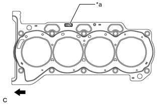
*a Lot No. 
Engine Front Place a new cylinder head gasket on the cylinder block sub-assembly with the Lot No. stamp facing upward.
Note
-
Remove any oil from the contact surface.
-
Pay attention to the mounting orientation of the cylinder head gasket.
-
Do not damage the cylinder gasket when installing the cylinder head onto the cylinder block.
-
-
-
INSTALL CYLINDER HEAD SUB-ASSEMBLY
Tech Tips
-
Perform "Inspection After Repair" after replacing the cylinder head sub-assembly.
-
The cylinder head bolts are tightened in 2 successive steps.
-
Apply a light coat of engine oil to the bolt threads and the area beneath the bolt heads that come incontact with the plate washers.
-
Install the 10 cylinder head set bolts and 10 plate washers to the cylinder head sub-assembly.
Note
Do not drop the plate washers into the cylinder head sub-assembly.
-
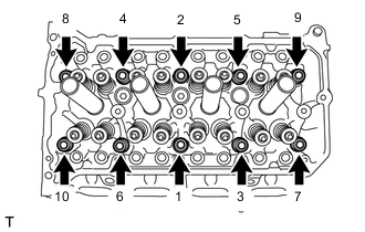
Using several steps, install and tighten the 10 cylinder head bolts and plate washers uniformly with a 10 mm bi-hexagon wrench in the sequence shown in the illustration.
- Torque:
- 49 N*m { 500 kgf*cm, 36 ft.*lbf }
-
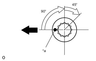
*a Paint Mark Engine Front Mark the front of the cylinder head bolt with paint.
-
Retighten the cylinder head bolts by additional 90° and one more additional 45° as shown in the illustration.
-
Check that the paint mark is now at a 135° angle from the front.
-
-
INSTALL NO. 1 WATER BY-PASS PIPE
-
Install the No. 1 water by-pass pipe to the cylinder head sub assembly with the 2 bolts.
- Torque:
- 21 N*m { 214 kgf*cm, 15 ft.*lbf }
-
-
INSTALL CAMSHAFT HOUSING SUB-ASSEMBLY
-
INSTALL VALVE LASH ADJUSTER ASSEMBLY
-
INSTALL NO. 1 VALVE ROCKER ARM SUB-ASSEMBLY
-
INSTALL NO. 2 CAMSHAFT
-
INSTALL CAMSHAFT
-
INSTALL CAMSHAFT BEARING CAP
-
INSTALL TIMING CHAIN OR BELT COVER SUB-ASSEMBLY