CAMSHAFT INSTALLATION

CAUTION / NOTICE / HINT
Tech Tips
Perform "Inspection After Repair" after replacing the camshaft, No. 2 camshaft, camshaft timing gear assembly or camshaft timing exhaust gear assembly.
PROCEDURE
-
INSTALL NO. 1 CAMSHAFT BEARING
-
Clean both surfaces of the 2 No. 1 camshaft bearings.
Note
Do not apply engine oil to the No. 1 camshaft bearings or the contact surfaces.
-
Install the 2 No. 1 camshaft bearings to the No. 1 camshaft bearing cap.
-
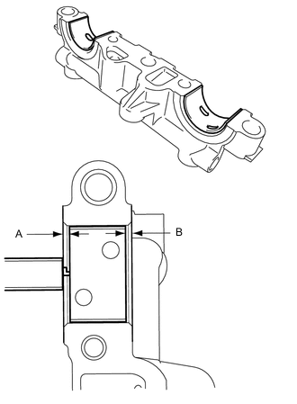
Using a vernier caliper, measure the distance between the No. 1 camshaft bearing cap edge and the No. 1 camshaft bearing edge.
Difference between (A) and (B) 0.7 mm (0.0276 in.) or less Note
Position the No. 1 camshaft bearings to the center of the No. 1 camshaft bearing cap by measuring dimensions A and B.
-
-
INSTALL NO. 2 CAMSHAFT BEARING
-
Clean both surfaces of the 2 No. 2 camshaft bearings.
Note
Do not apply engine oil to the No. 2 camshaft bearings or the contact surfaces.
-
Install the 2 No. 2 camshaft bearings to the camshaft housing sub-assembly.
-
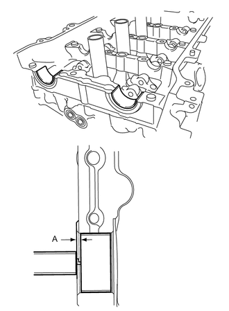
Using a vernier caliper, measure the distance between the camshaft housing sub-assembly edge and No. 2 camshaft bearing edge.
Dimension (A) 1.05 to 1.75 mm (0.0413 to 0.0689 in.) Note
Position the No. 2 camshaft bearings to the center of the camshaft housing sub-assembly by measuring dimension A.
-
-
INSTALL NO. 2 CAMSHAFT
-
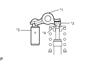
*1 No. 1 Valve Rocker Arm Sub-assembly *2 Valve Lash Adjuster Assembly *3 Valve Stem Cap *4 Valve Stem Make sure that the No. 1 valve rocker arm sub-assembly is installed as shown in the illustration.
-
Clean the camshaft journals.
-
Apply a light coat of engine oil to the No. 2 camshaft journals and camshaft housing sub-assembly.
-
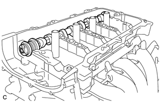
Install the No. 2 camshaft to the camshaft housing sub-assembly.
-
-
INSTALL CAMSHAFT
-

*1 No. 1 Valve Rocker Arm Sub-assembly *2 Valve Lash Adjuster Assembly *3 Valve Stem Cap *4 Valve Stem Make sure that the No. 1 valve rocker arm sub-assembly is installed as shown in the illustration.
-
Clean the camshaft journals.
-
Apply a light coat of engine oil to the camshaft journals, camshaft housing sub-assembly and camshaft bearing caps.
-
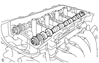
Install the camshaft to the camshaft housing sub-assembly.
-
-
INSTALL CAMSHAFT BEARING CAP
-
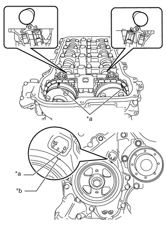
Check the marks and numbers on the camshaft bearing caps, and then remove the service bolts and spacers in the order shown in the illustration. Immediately after removing the service bolts and spacers, install the camshaft bearing caps with the 15 bolts in the order shown in the illustration.
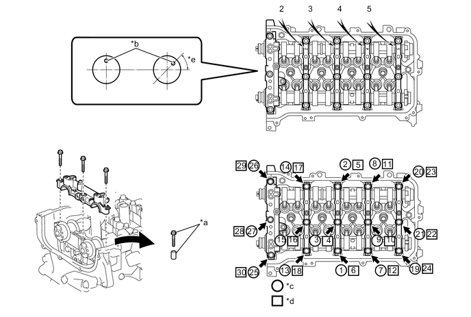
*a Service Bolt and Spacer (Used to temporarily secure the camshaft housing sub-assembly) *b Straight Pin *c The removal order of the service bolts and spacers for temporarily tightening the camshaft housing sub-assembly *d The installation order of the parts *e Approximately 50° - - - Torque:
- 27 N*m { 275 kgf*cm, 20 ft.*lbf }
Note
If the bolts are loosened all at once, FIPG on the camshaft housing sub-assembly and cylinder head sub-assembly may peel off, resulting in oil oozing. Therefore, be sure to remove the service bolts and spacers from one camshaft bearing cap at a time.
Tech Tips
Make sure that the orientation of the straight pin, timing mark and paint mark of the camshaft are as shown in the illustration.
-
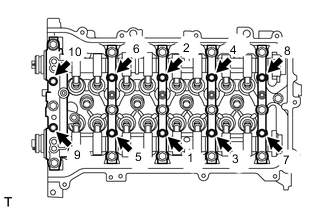
Tighten the 10 bolts in the order shown in the illustration.
- Torque:
- 16 N*m { 163 kgf*cm, 12 ft.*lbf }
-
Check the torque of each bolt again.
-
-
INSTALL CAMSHAFT TIMING GEAR ASSEMBLY
-
Check that the straight pin is installed on the camshaft.
-
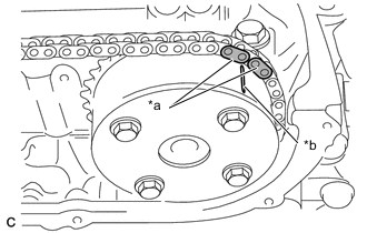
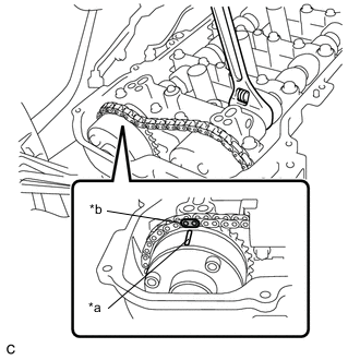
*a Paint Mark *b Timing Mark Hold up the chain sub-assembly and align the timing mark of the camshaft timing gear assembly and paint mark of the chain sub-assembly.
-
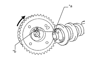
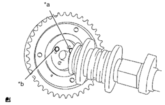
*a Straight Pin *b Key Groove Put the camshaft timing gear assembly and camshaft together with the straight pin and key groove misaligned, as shown in the illustration.
Note
Do not forcibly push in the camshaft timing gear assembly. This may cause the straight pin tip to damage the installation surface of the camshaft timing gear assembly.
-
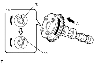
*a View A *b Straight Pin *c Key Groove Turn the camshaft timing gear assembly as shown in the illustration while pushing it gently against the camshaft. Push further at the position where the pin fits into the groove.
Note
Do not turn the camshaft timing gear assembly in the retard direction.
-
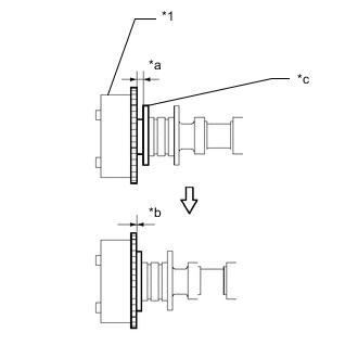
*1 Camshaft Timing Gear Assembly *a Clearance *b No Clearance *c Flange Check that there is no clearance between the camshaft timing gear assembly and camshaft flange.
-
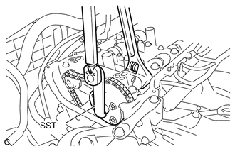
Using SST and a wrench, hold the hexagonal portion of the camshaft and install the camshaft timing gear assembly to the camshaft.
- SST
- 09249-37010
- Torque:
- Specified tightening torque
- 54 N*m { 551 kgf*cm, 40 ft.*lbf }
Note
When tightening the flange bolt, do not allow the camshaft timing gear assembly to rotate.
Tech Tips
-
Calculate the torque wrench reading when changing the fulcrum length of the torque wrench.
-
When using SST (fulcrum length of 100 mm (3.94 in.)) + torque wrench (fulcrum length of 255 mm (10.0 in.)):
38.8 N*m (396 kgf*cm, 29 ft.*lbf)
-
*a Lock Check that the camshaft timing gear assembly can move to the retard angle side and is locked in the most retarded position.
Tech Tips
Perform "Inspection After Repair" after replacing the camshaft timing gear assembly.
-
-
INSTALL CAMSHAFT TIMING EXHAUST GEAR ASSEMBLY
-
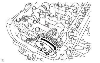
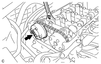
*a Timing Mark *b Paint Mark Hold the hexagonal portion of the camshaft with a wrench and turn it slightly counterclockwise to release the chain sub-assembly.
Note
Do not turn the camshaft more than necessary.
-
Check that the straight pin is installed on the No. 2 camshaft.
-
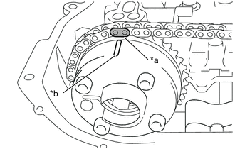
*a Paint Mark *b Timing Mark Hold up the chain sub-assembly and align the timing mark of the camshaft timing exhaust gear assembly and paint mark of the chain sub-assembly.
-
*a Straight Pin *b Key Groove Put the camshaft timing exhaust gear assembly and No. 2 camshaft together by aligning the key groove and straight pin.
Note
-
If the straight pin cannot be aligned with the key groove, hold the hexagonal portion of the No. 2 camshaft with a wrench and turn it slightly to install the camshaft timing exhaust gear assembly.
-
Do not turn the No. 2 camshaft more than necessary.
-
Do not forcibly push in the camshaft timing exhaust gear assembly. This may cause the straight pin tip to damage the installation surface of the camshaft timing exhaust gear assembly.
-
-
Hold the hexagonal portion of the No. 2 camshaft and tighten the flange bolt of the camshaft timing exhaust gear assembly.
- Torque:
- 54 N*m { 551 kgf*cm, 40 ft.*lbf }
-
-
INSTALL NO. 2 CHAIN VIBRATION DAMPER
-
Install the No. 2 chain vibration damper to the No. 1 camshaft bearing cap with the 2 bolts.
- Torque:
- 10 N*m { 102 kgf*cm, 7 ft.*lbf }
-
-
INSTALL NO. 1 CHAIN TENSIONER ASSEMBLY
-
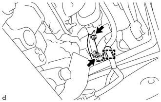
Install the wire harness clamp bracket and No. 1 chain tensioner assembly with the 2 nuts.
- Torque:
- 10 N*m { 102 kgf*cm, 7 ft.*lbf }
-
Engage the clamp and connect the wire harness.
-
-
INSTALL SERVICE COVER
-
Remove any remaining seal packing material.
-
Clean the contact surfaces of the timing chain cover sub-assembly and service cover, and confirm that no oil, moisture, or other foreign matter is on the surfaces.
-
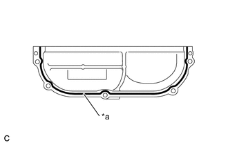
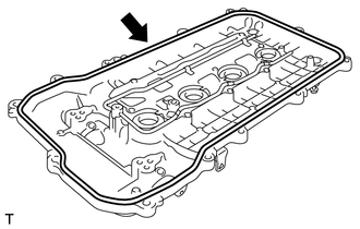
*a Seal Packing Black Apply seal packing in a continuous line as shown in the illustration.
Seal Packing Toyota Genuine Seal Packing Black, Three Bond 1207B or equivalent Standard Diameter 5.0 mm (0.197 in.) Note
-
Remove any oil from the contact surfaces.
-
Install the service cover within 3 minutes and tighten the bolts within 10 minutes of applying seal packing.
-
Do not add engine oil for at least 2 hours after installing the service cover.
-
-
Install the service cover to the timing chain cover sub-assembly with the 5 bolts.
- Torque:
- 9.1 N*m { 93 kgf*cm, 81 in.*lbf }
-
-
SET NO. 1 CYLINDER TO TDC / COMPRESSION
-
*a Timing Mark *b Timing Notch Turn the crankshaft pulley until its timing notch (groove) and the timing mark "0" of the timing chain cover sub-assembly are aligned.
-
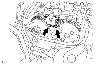
Check that each timing mark of the camshaft timing gear assembly and camshaft timing exhaust gear assembly are aligned as shown in the illustration.
If not, turn the crankshaft 1 revolution (360°) to align the timing marks as shown in the illustration.
-
-
INSTALL CYLINDER HEAD COVER GASKET
-
Install a new cylinder head cover gasket to the cylinder head cover sub-assembly.
Note
Remove any oil from the contact surfaces.
-
-
INSTALL CYLINDER HEAD COVER SUB-ASSEMBLY
-
Install 2 new gaskets and O-ring to the No. 1 camshaft bearing cap.
-
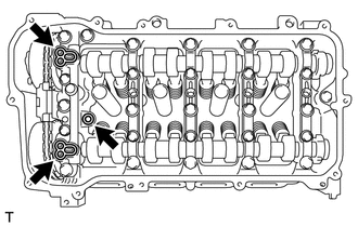
Apply seal packing as shown in the illustration.
Seal Packing Toyota Genuine Seal Packing Black, Three Bond 1207B or equivalent Standard Diameter 4.0 mm (0.157 in.) Note
-
Remove any oil from the contact surfaces.
-
Install the cylinder head cover sub-assembly within 3 minutes and tighten the bolts within 15 minutes of applying seal packing.
-
Do not start the engine for at least 2 hours after installing the cylinder head cover sub-assembly.
-
-
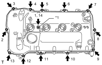
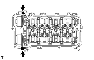
*1 Seal Washer Install the cylinder head cover sub-assembly to the camshaft housing sub-assembly with the 13 bolts and a new seal washer in the order shown in the illustration.
- Torque:
- 10 N*m { 102 kgf*cm, 7 ft.*lbf }
-
-
INSTALL AIR TUBE
-
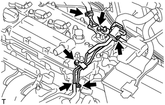
Install the air tube with the 2 bolts.
- Torque:
- 10 N*m { 102 kgf*cm, 7 ft.*lbf }
-
Connect the 4 hoses.
-
-
CONNECT INTERCOOLER RESERVE TANK ASSEMBLY
-
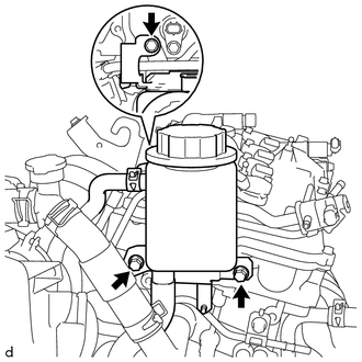
Connect the intercooler reserve tank assembly with the 3 bolts.
- Torque:
- 20 N*m { 204 kgf*cm, 15 ft.*lbf }
-
-
CONNECT ENGINE WIRE
-
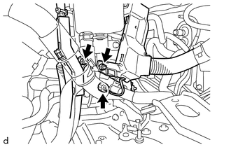
Connect the engine wire with the 2 nuts.
- Torque:
- 8.4 N*m { 86 kgf*cm, 74 in.*lbf }
-
Connect the connector.
-
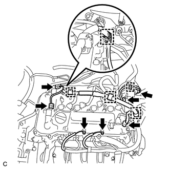
Install the 2 bolts.
- Torque:
- 8.4 N*m { 86 kgf*cm, 74 in.*lbf }
-
Engage the 5 clamps.
-
Connect the 5 connectors.
-
-
CONNECT NO. 2 VENTILATION HOSE
-
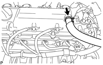
Connect the No. 2 ventilation hose to the cylinder head cover sub-assembly and slide the hose clip to secure it.
-
-
INSTALL IGNITION COIL ASSEMBLY
-
INSPECT FOR OIL LEAK
-
INSTALL OUTER COWL TOP PANEL (for LHD)
-
INSTALL OUTER COWL TOP PANEL (for RHD)
-
INSTALL INNER COWL TOP TO COWL BRACE (for LHD)
-
INSTALL INNER COWL TOP TO COWL BRACE (for RHD)
-
INSTALL FRONT AIR SHUTTER SEAL RH (for LHD)
-
INSTALL FRONT AIR SHUTTER SEAL RH (for RHD)
-
INSTALL FRONT NO. 1 VENTILATOR SEAL (for LHD)
-
INSTALL FRONT NO. 1 VENTILATOR SEAL (for RHD)
-
INSTALL WINDSHIELD WIPER MOTOR AND LINK ASSEMBLY
-
INSPECT ENGINE IDLE SPEED