CYLINDER BLOCK REASSEMBLY

CAUTION / NOTICE / HINT
Tech Tips
Perform "Inspection After Repair" after replacing the piston with pin sub-assembly or piston ring set.
PROCEDURE
-
INSTALL NO. 1 OIL NOZZLE SUB-ASSEMBLY
-
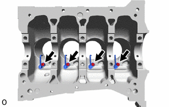
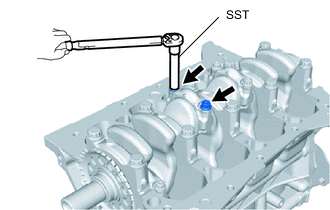
Using a 5 mm hexagon wrench, install the 4 No. 1 oil nozzle sub-assemblies with the 4 bolts.
- Torque:
- 10 N*m { 102 kgf*cm, 7 ft.*lbf }
-
-
INSTALL PISTON
Note
If the piston pin has been removed from the piston, replace the piston, piston pin and connecting rod with new ones.
-
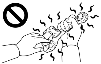
Gradually heat the connecting rod to 80°C (176°F) or higher.
Note
-
Do not touch the connecting rod without wearing protective gloves, as it may get very hot during operation.
-
Be sure to wear protective gloves to avoid burns.
-
-
Apply a light coat of engine oil to the new piston, piston pin and connecting rod.
-
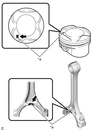
*a Front Mark Align the front marks of the piston and connecting rod.
-
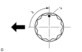
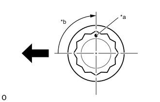
Using SST, press in the piston pin.
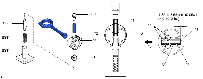
*1 Piston Pin *2 Connecting Rod *3 Piston - - *a Front Mark *b Rear Side *c Contact - - - SST
- 09221-25026 ( 09221-00021, 09221-00030, 09221-00090, 09221-00100, 09221-00150 )
Note
-
Press in the piston pin from the side of the piston with the front mark facing as shown in the illustration.
-
With the connecting rod fully inserted into the piston end, press in the piston pin until it is flush with the piston surface.
-
Check the fitting condition between the piston and piston pin by trying to move the piston back and forth on the piston pin.
-
-
INSTALL PISTON RING SET
-
*1 Upper Side Rail *2 Expander Spacer *3 Lower Side Rail *a Expander Spacer and Side Rail Groove Install the oil ring expander, upper side rail and lower side rail by hand.
-
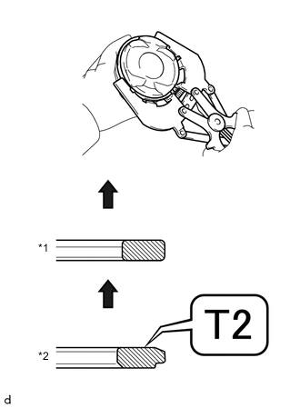
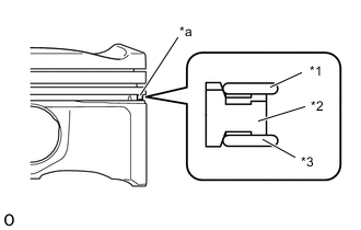
*1 No. 1 Compression Ring *2 No. 2 Compression Ring 
Upward Using a piston ring expander, install the No. 1 compression ring and No. 2 compression ring with the code mark positioned as shown in the illustration.
Note
Install the No. 2 compression ring with the code mark (T2) facing upward.
-
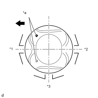
*1 No. 1 Compression Ring and Upper Side Rail *2 No. 2 Compression Ring and Lower Side Rail *3 Expander Spacer *a Front Mark Engine Front Position the piston rings so that the ring ends are as shown in the illustration.
-
-
INSTALL CRANKSHAFT BEARING
-
Clean the main journal and both surfaces of the crankshaft bearings.
-
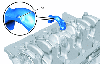
Install the 5 crankshaft bearings to the cylinder block sub-assembly as shown in the illustration.
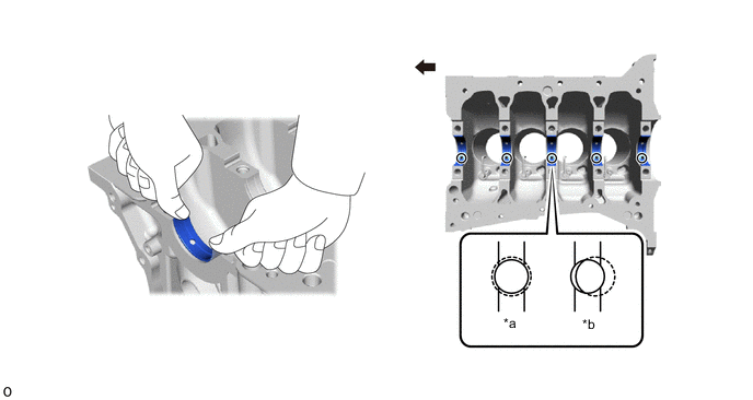
*a Correct *b Incorrect Engine Front - - Note
-
Do not apply engine oil to the crankshaft bearings or the contact surfaces.
-
Both sides of the oil groove in the cylinder block sub-assembly should be visible through the oil feed holes in the crankshaft bearing. The amount visible on each side of the holes should be equal.
-
-
Install the 5 crankshaft bearings to the crankshaft bearing caps.
-
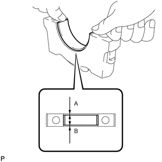
Using a vernier caliper, measure the distance between the crankshaft bearing cap edge and the crankshaft bearing edge.
Difference between (A) and (B) 0.8 mm (0.0315 in.) or less Note
Do not apply engine oil to the crankshaft bearings or the contact surfaces.
-
-
-
INSTALL CRANKSHAFT
-
Apply engine oil to the upper crankshaft thrust washers.
-
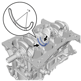
*a Oil Groove Install the 2 upper crankshaft thrust washers to the No. 3 journal position of the cylinder block sub-assembly with the oil grooves facing outward.
Note
Ensure that the orientation of the upper crankshaft thrust washer upper is correct.
-
Apply engine oil to the crankshaft bearings and place the crankshaft on the cylinder block sub-assembly.
-
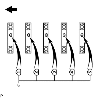
*a Front Mark and Number Mark Engine Front Confirm the front marks and number marks, and install the 5 crankshaft bearing caps to the cylinder block sub-assembly with the marks facing as shown in the illustration.
-
Apply a light coat of engine oil to the threads and under the heads of the crankshaft bearing cap set bolts.
-
Temporarily install the 5 crankshaft bearing caps with the 10 crankshaft bearing cap set bolts..
-
Step 1:
-
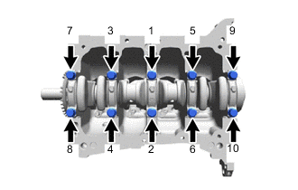
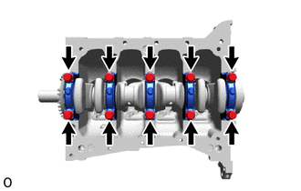
Uniformly tighten the 10 crankshaft bearing cap set bolts in several steps in the order shown in the illustration.
- Torque:
- 30 N*m { 306 kgf*cm, 22 ft.*lbf }
-
-
Step 2:
-
*a Paint Mark *b 90° Engine Front Mark the front of the crankshaft bearing cap set bolts with paint.
-
Tighten the crankshaft bearing cap set bolts by 90° in the order shown in the illustration.
-
-
Check that the paint marks are now at a 90° angle to the front.
-
Check that the crankshaft turns smoothly.
-
-
INSTALL CONNECTING ROD BEARING
-
Clean the connecting rod bearing contact surface of the connecting rod and connecting rod bearing cap, and both surfaces of both connecting rod bearings.
-
Install the connecting rod bearings to the connecting rod and connecting rod bearing cap.
-
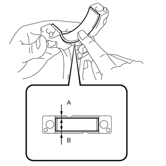
Using a vernier caliper, measure the distance between the edges of the connecting rod and connecting rod bearing, and the edges of the connecting rod bearing cap and connecting rod bearing.
Difference between (A) and (B) 0.5 mm (0.0197 in.) or less Note
Do not apply engine oil to the connecting rod bearings or the contact surfaces.
-
-
INSTALL PISTON SUB-ASSEMBLY WITH CONNECTING ROD
-
Apply engine oil to the cylinder walls, pistons, and surfaces of the connecting rod bearings.
-
*1 No. 1 Compression Ring and Upper Side Rail *2 No. 2 Compression Ring and Lower Side Rail *3 Expander Spacer *a Front Mark Engine Front Position the piston rings so that the ring ends are as shown in the illustration.
-

*a Front Mark Using a hammer handle and piston ring compressor, press the piston sub-assembly with connecting rod into each cylinder with the front mark of the piston facing the engine front.
Note
-
When inserting the piston sub-assembly with connecting rod into the cylinder block sub-assembly, make sure the No. 1 oil nozzle sub-assembly does not interfere with the connecting rod.
-
Install the same parts to their original positions.
-
-
*a Front Mark Check that the front mark of the connecting rod bearing cap is facing in the correct direction.
-
Install the connecting rod bearing cap to the connecting rod.
-
Apply a light coat of engine oil to the threads and under the heads of the 2 connecting rod bolts.
-
Temporarily install the 2 connecting rod bolts.
-
Step 1:
-
Using SST, alternately tighten the 2 connecting rod bolts in several steps.
- SST
- 09205-16011
- Torque:
- 15 N*m { 153 kgf*cm, 11 ft.*lbf }
-
-
Step 2:
-
*a Paint Mark *b 90° Engine Front Mark the front of the 2 connecting rod bolts with paint.
-
Tighten the connecting rod bolts by 90° as shown in the illustration.
-
Check that the paint marks are now at a 90° angle to the front.
-
-
Check that the crankshaft turns smoothly.
-