CYLINDER BLOCK REPLACEMENT

PROCEDURE
-
REPLACE RING PIN
Note
It is not necessary to remove the ring pins unless they are being replaced.
-
Remove the 2 ring pins.
-
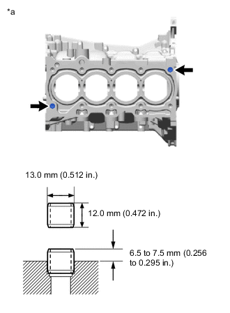
*a Cylinder Block Sub-assembly Upper Side Using a plastic hammer, install the 2 ring pins.
Standard Protrusion Height 6.5 to 7.5 mm (0.256 to 0.295 in.)
-
-
REPLACE STRAIGHT PIN
Note
It is not necessary to remove the straight pins unless they are being replaced.
-
Remove the 5 straight pins.
-
Using a plastic hammer, install 5 new straight pins to the cylinder block sub-assembly.
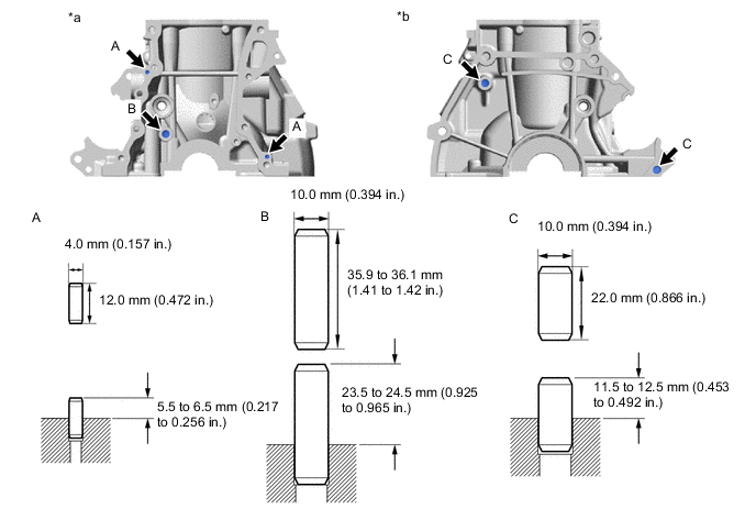
*a Cylinder Block Sub-assembly Front Side *b Cylinder Block Sub-assembly Rear Side
-