CYLINDER BLOCK DISASSEMBLY

PROCEDURE
-
REMOVE PISTON SUB-ASSEMBLY WITH CONNECTING ROD
-
Mark the corresponding cylinder number on each connecting rod and connecting rod bearing cap with paint.
Tech Tips
The paint marks are used to ensure that the same parts are installed in the same combination to their original locations.
-
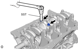
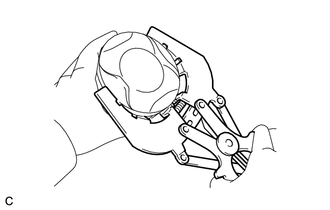
Using SST, remove the 2 connecting rod bolts from the connecting rod bearing cap.
- SST
- 09205-16011
-
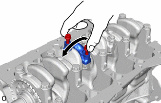
Using the 2 removed connecting rod bolts, remove the connecting rod bearing cap and connecting rod bearing by wiggling the connecting rod bearing cap right and left.
-
Push out the 4 piston sub-assembly with connecting rods and connecting rod bearing through the top of the cylinder block sub-assembly.
-
-
REMOVE CONNECTING ROD BEARING
-
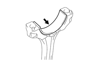
Remove the 4 connecting rod bearings from the connecting rod.
Tech Tips
Arrange the removed parts in the correct order.
-
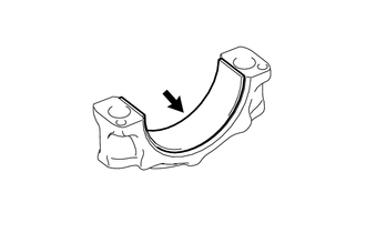
Remove the 4 connecting rod bearings from the connecting rod bearing cap.
Tech Tips
Arrange the removed parts in the correct order.
-
-
REMOVE PISTON RING SET
-
Using a piston ring expander, remove the No. 1 compression ring and No. 2 compression ring from the piston.
-
Remove the expander spacer, upper side rail and lower side rail by hand from the piston.
-
-
REMOVE CRANKSHAFT
-
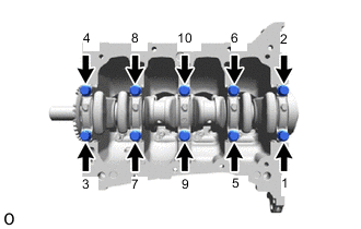
Uniformly loosen and remove the 10 crankshaft bearing cap set bolts in several steps in the order shown in the illustration.
-
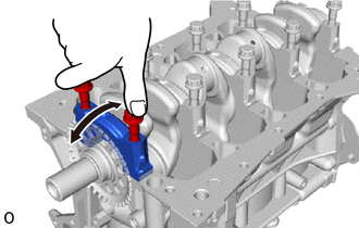
Using the 2 removed crankshaft bearing cap set bolts, remove the 5 crankshaft bearing caps from the cylinder block sub-assembly by wigging each crankshaft bearing cap back and forth.
-
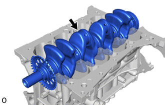
Remove the crankshaft from the cylinder block sub-assembly.
-
-
REMOVE UPPER CRANKSHAFT THRUST WASHER
-
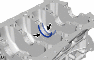
Remove the 2 upper crankshaft thrust washers from the cylinder block sub-assembly.
-
-
REMOVE CRANKSHAFT BEARING
-
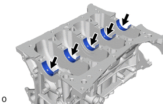
Remove the 5 crankshaft bearings from the cylinder block sub-assembly.
Tech Tips
Arrange the removed parts in the correct order.
-
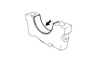
Remove the 5 crankshaft bearings from the 5 crankshaft bearing caps.
Tech Tips
Arrange the removed parts in the correct order.
-
-
REMOVE NO. 1 OIL NOZZLE SUB-ASSEMBLY
-
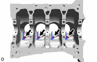
Using a 5 mm hexagon wrench, remove the 4 bolts and 4 No. 1 oil nozzle sub-assemblies from the cylinder block sub-assembly.
-