PROCEDURE
- Click here
INSTALL SPARK PLUG TUBE
Tip:When replacing the cylinder head sub-assembly with a new one, perform the following procedure.
-
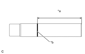
*a Protrusion Height *b Paint Mark Mark the standard protrusion height from the edge with paint.
Standard Protrusion Height 88.7 to 90.2 mm (3.49 to 3.55 in.) -
Clean and degrease the spark plug tube holes.
-
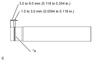
*a Adhesive 1324 Apply adhesive to each spark plug tube where it will be pressed into the cylinder head sub-assembly.
Adhesive Toyota Genuine Adhesive 1324, Three Bond 1324 or equivalent Note:To prevent contamination by foreign matter, install immediately after applying adhesive.
-
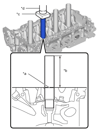
*a Mark *b Protrusion Height *c Wooden Block *d Press Using a press and wooden block, install the 4 spark plug tubes to the specified protrusion height.
Standard Protrusion Height 88.7 to 90.2 mm (3.49 to 3.55 in.) Note:
-
Do not insert to bottom.
-
Do not start the engine within 1 hour after installation.
-
Be careful not to deform the spark plug tube.
-
Ensure that no adhesive drips inside the cylinder head sub-assembly.
-
-
- Click here
INSTALL VALVE SPRING SEAT
-
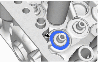
Install the 16 valve spring seats to the cylinder head sub-assembly.
-
- Click here
INSTALL VALVE STEM OIL SEAL
-
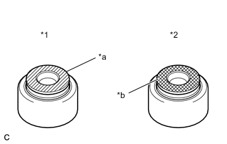
*1 Intake Valve Stem Oil Seal *2 Exhaust Valve Stem Oil Seal *a Gray *b Black Apply a light coat of engine oil to new valve stem oil seals.
Note:Pay attention when installing the valve stem oil seals. For example, installing an intake valve stem oil seal onto the exhaust side or installing an exhaust valve stem oil seal onto the intake side can cause installation problems later.
Tip:The intake valve stem oil seals are gray and the exhaust valve stem oil seals are black.
-
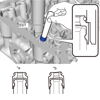
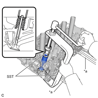
*a Correct *b Incorrect Using SST, push in the 16 valve stem oil seals.
09201-41020 Note:Failure to use SST will cause the valve stem oil seal to be damaged or improperly seated.
-
- Click here
INSTALL INTAKE VALVE
-
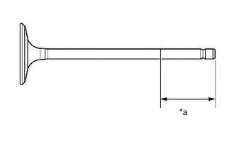
*a 30 mm (1.18 in.) or more Sufficiently apply engine oil to the tip area of the intake valve shown in the illustration.
-
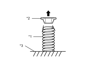
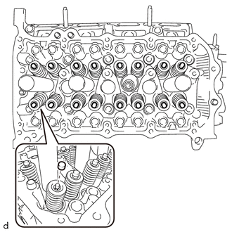
*1 Outer Compression Spring *2 Valve Spring Retainer *3 Cylinder Head Sub-assembly 
Upper Side Install the 8 intake valves, 8 outer compression springs and 8 valve spring retainers to the cylinder head sub-assembly.
Note:
-
Install the outer compression spring with its tapered side facing upward (towards the valve spring retainer).
-
Install the same parts to their original positions.
-
-
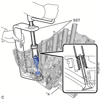
*a Wooden Block Using SST and wooden blocks, compress the outer compression spring and install the 16 valve spring retainer locks.
09202-70020 09202-01010 09202-01020 09202-00021 Note:Install the same parts to their original positions.
-
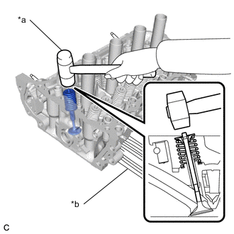
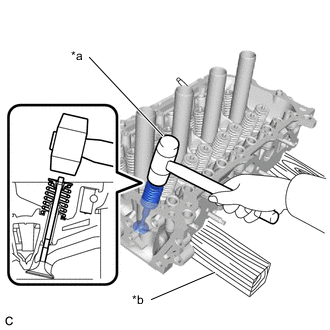
*a Plastic Hammer *b Wooden Block Using a plastic hammer, lightly tap the intake valve stem tip to ensure a proper fit.
Note:
-
Be careful not to damage the intake valve stem tip.
-
Be careful not to tap the retainer.
-
-
- Click here
INSTALL EXHAUST VALVE
-
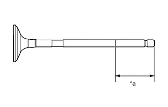
*a 30 mm (1.18 in.) or more Sufficiently apply engine oil to the tip area of the exhaust valve shown in the illustration.
-
*1 Outer Compression Spring *2 Valve Spring Retainer *3 Cylinder Head Sub-assembly Upper Side Install the 8 exhaust valves, 8 outer compression springs and 8 valve spring retainers to the cylinder head sub-assembly.
Note:
-
Install the outer compression spring with its tapered side facing upward (towards the valve spring retainer).
-
Install the same parts to their original positions.
-
-
*a Wooden Block Using SST and wooden blocks, compress the outer compression spring and install the 16 valve spring retainer locks.
09202-70020 09202-01010 09202-01020 09202-00021 Note:Install the same parts to their original positions.
-
*a Plastic Hammer *b Wooden Block Using a plastic hammer, lightly tap the exhaust valve stem tip to ensure a proper fit.
Note:
-
Be careful not to damage the exhaust valve stem tip.
-
Be careful not to tap the retainer.
-
-
- Click here
INSTALL VALVE STEM CAP
-
Apply a light coat of engine oil to the end of the valve stem.
-
Install the 16 valve stem caps to the intake valves and exhaust valves.
Note:Install the same parts to their original positions.
-