FUEL INJECTOR INSTALLATION

PROCEDURE
-
INSTALL FUEL INJECTOR ASSEMBLY
-
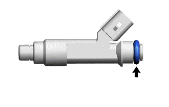
Apply a light coat of gasoline or spindle oil to new O-rings, and then install one to each fuel injector assembly.
-
Apply a light coat of gasoline or spindle oil where the fuel delivery pipe contacts each O-ring.
-
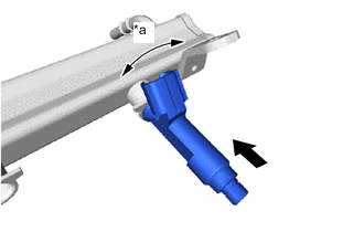
Text in Illustration *a Turn 
Push While turning the fuel injector assembly left and right, install it to the fuel delivery pipe.
Note
-
Do not damage the fuel injector assembly or O-ring.
-
Do not twist the O-ring.
-
After installing each fuel injector assembly, check that it turns smoothly. If not, replace the O-ring with a new one.
Tech Tips
Use the some procedure to install the other fuel injector assemblies.
-
-
-
INSTALL FUEL PIPE INSULATOR
-
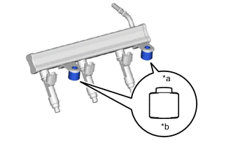
Text in Illustration *a fuel delivery pipe Side *b Cylinder Head Sub-assembly Side Install the 2 fuel pipe insulators to the cylinder head sub-assembly.
Note
Install the fuel pipe insulators in the correct direction.
-
-
INSTALL INJECTOR VIBRATION INSULATOR
-
Install 3 new injector vibration insulators to the cylinder head sub-assembly.
-
-
INSTALL FUEL DELIVERY PIPE
-
Install the fuel delivery pipe together with 3 fuel injector assemblies to the cylinder head sub-assembly with the 2 bolts.
- Torque:
- 27 N*m { 275 kgf*cm, 20 ft.*lbf }
Note
-
Do not drop the fuel injector assemblies when installing the fuel delivery pipe.
-
After installing the fuel delivery pipe, check that the fuel injector assemblies turn smoothly.
Tech Tips
The No. 2 fuel pipe clamp is designed so that it cannot be installed if the fuel tube connector is improperly connected.
-
Install the wire harness clamp bracket to the intake manifold with the bolt.
- Torque:
- 8.4 N*m { 86 kgf*cm, 74 in.*lbf }
-
Engage the clamp to connect the wire harness to the wire harness clamp bracket.
-
Connect the 3 fuel injector assembly connectors.
-
Connect the throttle body with motor assembly connector.
-
-
INSTALL FUEL TUBE SUB-ASSEMBLY
Note
Check if there is any damage or foreign matter on the connecting parts of the fuel lines.
-
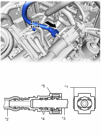
Text in Illustration *1 Retainer *2 Nylon Tube *3 Fuel Pipe *4 O-ring *5 Fuel Tube Connector Push Connect the fuel tube sub-assembly to the fuel delivery pipe.
-
Align the fuel tube connector with the fuel pipe, and push them together until the fuel tube connector makes a "click" sound. If it is difficult to push the fuel pipe into the fuel tube connector, apply a small amount of clean engine oil to the tip of the fuel pipe and reinsert it.
-
After connecting the fuel lines, check that the fuel pipe and fuel tube connector are securely connected by pulling on them.
-
Engage the clamp to connect the fuel tube sub-assembly to the fuel pipe clamp.
-
-
-
INSTALL EFI FUEL PIPE CLAMP
-
Install the EFI fuel pipe clamp to the fuel tube sub-assembly and fuel delivery pipe.
-
-
INSTALL CYLINDER HEAD COVER GASKET
-
INSTALL CYLINDER HEAD COVER SUB-ASSEMBLY
-
CONNECT ENGINE WIRE
-
INSTALL DUTY VACUUM SWITCHING VALVE
-
INSTALL NO. 1 IGNITION COIL
-
INSTALL AIR CLEANER FILTER ELEMENT SUB-ASSEMBLY
-
INSTALL AIR CLEANER CAP SUB-ASSEMBLY
-
INSTALL INLET NO. 1 AIR CLEANER
-
INSPECT ENGINE OIL LEVEL
-
INSPECT FOR ENGINE OIL LEAK
-
INSPECT FOR FUEL LEAK