FUEL INJECTOR REMOVAL

PROCEDURE
-
DISCHARGE FUEL SYSTEM PRESSURE
-
REMOVE INLET NO. 1 AIR CLEANER
-
REMOVE AIR CLEANER CAP SUB-ASSEMBLY
-
REMOVE AIR CLEANER FILTER ELEMENT SUB-ASSEMBLY
-
REMOVE NO. 1 IGNITION COIL
-
SEPARATE DUTY VACUUM SWITCHING VALVE
-
SEPARATE ENGINE WIRE
-
REMOVE CYLINDER HEAD COVER SUB-ASSEMBLY
-
REMOVE CYLINDER HEAD COVER GASKET
-
REMOVE EFI FUEL PIPE CLAMP
Note
Before disconnecting the fuel tube connector, make sure there are no deposits, clean them away.
-
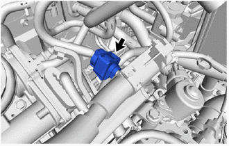
Remove the EFI fuel pipe clamp from the fuel tube sub-assembly and fuel delivery pipe.
-
-
DISCONNECT FUEL TUBE SUB-ASSEMBLY
-
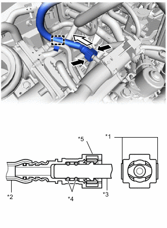
Text in Illustration *1 Retainer *2 Nylon Tube *3 Fuel Pipe *4 O-ring *5 Fuel Tube Connector 
Pinch 
Pull Disconnect the fuel tube sub-assembly from the fuel delivery pipe.
-
Disengage the clamp to disconnect the fuel tube sub-assembly from the fuel hose clamp.
-
Pinch the retainer of the fuel tube connector, and then pull the fuel tube connector off of the fuel pipe.
Note
Be sure to disconnect the fuel tube connector by hand.
-
If the fuel tube connector and fuel pipe are stuck, push and pull the fuel tube connector to release it. Pull the fuel tube connector off of the fuel pipe carefully.
Note
-
Be sure to disconnect the fuel tube connector by hand.
-
Do not allow any scratches or foreign matter to get on the parts when disconnecting them as the fuel tube connector has O-rings that seal the fuel pipe.
-
Do not forcibly bend, twist or turn the nylon tube.
-
-
Check if there is any foreign matter on the sealing surfaces of the disconnected fuel lines. Clean them if necessary.
-
Cover the disconnected fuel tube connector and fuel pipe with plastic bags to prevent damage and contamination.
-
-
-
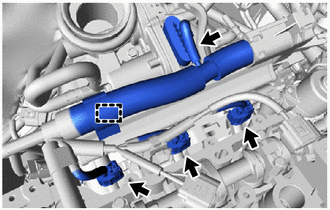
REMOVE FUEL DELIVERY PIPE
-
Make sure that there are no deposits such as sand or grit near the fuel injector assembly, and if there are any deposits, clean them away.
Note
Do not allow foreign matter to enter any other components.
-
Disconnect the throttle body with motor assembly connector.
-
Disengage the 3 fuel injector assembly connectors.
-
Disengage the clamp to disconnect the wire harness from the wire harness clamp bracket.
-
Remove the bolt and wire harness clamp bracket from the intake manifold.
-
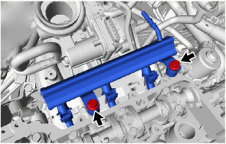
Remove the 2 bolts and fuel delivery pipe together with 3 fuel injector assemblies from the cylinder head sub-assembly.
Note
-
Do not allow foreign matter to enter the cylinder head sub-assembly.
-
Do not drop the fuel injector assemblies when removing the fuel delivery pipe.
-
-
-
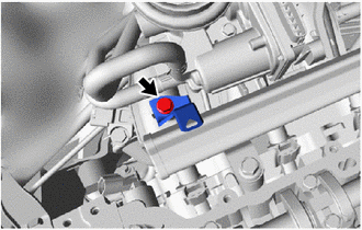
REMOVE INJECTOR VIBRATION INSULATOR
-
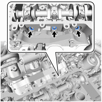
Remove the 3 injector vibration insulators from the cylinder head sub-assembly.
-
-
REMOVE FUEL PIPE INSULATOR
-
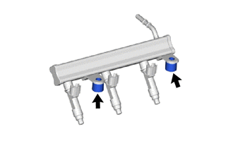
Remove the 2 fuel pipe insulators from the fuel delivery pipe.
Note
Do not allow foreign matter to enter the fuel delivery pipe.
-
-
REMOVE FUEL INJECTOR ASSEMBLY
-
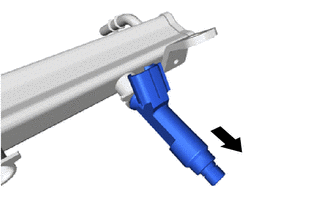
Pull the 3 fuel injector assemblies out of the fuel delivery pipe.
Note
Do not allow foreign matter to enter the fuel delivery pipe.
-
Remove the O-ring from each fuel injector assembly.
-
For reinstallation, attach a tag or label with the corresponding cylinder number to each fuel injector assembly.
Note
Protect the fuel injector assemblies by covering them with plastic bags.
-